Download
1 / 40
400 likes | 530 Views
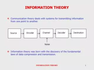
Tutorial on Information Theory. Network/Link Design Factors. Bandwidth Higher bandwidth gives higher data rate Transmission impairments Attenuation Interference Number of receivers In guided media More receivers (multi-point) introduce more attenuation. Channel Capacity. Data rate

E N D
Network/Link Design Factors • Bandwidth • Higher bandwidth gives higher data rate • Transmission impairments • Attenuation • Interference • Number of receivers • In guided media • More receivers (multi-point) introduce more attenuation
Channel Capacity • Data rate • In bits per second • Rate at which data can be communicated • Bandwidth • In cycles per second, or Hertz • Constrained by transmitter and medium
Data Rate and Bandwidth • Any transmission system has a limited band of frequencies • This limits the data rate that can be carried
The Electromagnetic Spectrum The electromagnetic spectrum and its uses for communication.
Sine Wave • Peak Amplitude (A) • maximum strength of signal • volts • Frequency (f) • Rate of change of signal • Hertz (Hz) or cycles per second • Period = time for one repetition (T) • T = 1/f • Phase () • Relative position in time
Figure 1.8 Modes of transmission: (b) modulated transmission
Encoding • Signals propagate over a physical medium • modulate electromagnetic waves • e.g., vary voltage • Encode binary data onto signals • e.g., 0 as low signal and 1 as high signal • known as Non-Return to zero (NRZ)
Other Encoding Schemes • Nonreturn to Zero-Level (NRZ) Unipolar • Nonreturn to Zero-Level (NRZ) Polar • Nonreturn to Zero Inverted (NRZI) • Bipolar -AMI • Manchester • Differential Manchester
0 1 0 1 1 1 1 0 0 Unipolar NRZ Polar NRZ NRZ-Inverted (Differential Encoding) Bipolar Encoding Manchester Encoding Differential Manchester Encoding Figure 3.25
Digital Data, Analog Signal • Use modem (modulator-demodulator) • Amplitude shift keying (ASK) • Frequency shift keying (FSK) • Phase shift keying (PSK)
Quadrature PSK • More efficient use by each signal element representing more than one bit • e.g. shifts of /2 (90o) • Each element represents two bits • Can use 8 phase angles and have more than one amplitude • 9600bps modem use 12 angles , four of which have two amplitudes
Modems (2) (a) QPSK. (b) QAM-16. (c) QAM-64.
Modems (3) (a) V.32 for 9600 bps. (b) V32 bis for 14,400 bps. (b) (a)
2-D signal Bk Ak 4 “levels”/ pulse 2 bits / pulse 2W bits per second Bk 2-D signal Ak 16 “levels”/ pulse 4 bits / pulse 4W bits per second Figure 3.33
Bk Bk Ak Ak 16 “levels”/ pulse 4 bits / pulse 4W bits per second 4 “levels”/ pulse 2 bits / pulse 2W bits per second Figure 3.34
Nyquist Bandwidth • If rate of signal transmission is 2B then signal with frequencies no greater than B is sufficient to carry signal rate • Given bandwidth B, highest signal rate is 2B • Given binary signal, data rate supported by B Hz is 2B bps • Can be increased by using M signal levels • C= 2B log2M
Transmission Impairments • Signal received may differ from signal transmitted • Analog - degradation of signal quality • Digital - bit errors • Caused by • Attenuation and attenuation distortion • Delay distortion • Noise
Attenuation • Signal strength falls off with distance • Depends on medium • Received signal strength: • must be enough to be detected • must be sufficiently higher than noise to be received without error • Attenuation is an increasing function of frequency
Noise (1) • Additional signals inserted between transmitter and receiver • Thermal • Due to thermal agitation of electrons • Uniformly distributed • White noise • Intermodulation • Signals that are the sum and difference of original frequencies sharing a medium
Noise (2) • Crosstalk • A signal from one line is picked up by another • Impulse • Irregular pulses or spikes • e.g. External electromagnetic interference • Short duration • High amplitude
signal + noise signal noise High SNR t t t noise signal + noise signal Low SNR t t t Average Signal Power SNR = Average Noise Power SNR (dB) = 10 log10 SNR Figure 3.12
Shannon’s Theorem Real communication have some measure of noise. This theorem tells us the limits to a channel’s capacity (in bits per second) in the presence of noise. Shannon’s theorem uses the notion of signal-to-noise ratio (S/N), which is usually expressed in decibels (dB):
Shannon’s Theorem – cont. Shannon’s Theorem: C: achievable channel rate (bps) B: channel bandwidth For POTS, bandwidth is 3000 Hz (upper limit of 3300 Hz and lower limit of 300 Hz), S/N = 1000