Download
1 / 13
140 likes | 577 Views
GMAW / Mig Welding . Basic equipment setup and welding procedures . Gas Metal Arc Welding . Is a process where a continuously fed metal electrode ( Wire ) contacts the base metal and produces heat . The arc is shielded by an inert gas . GMAW Components . DC or Direct Current power supply

E N D
GMAW / Mig Welding Basic equipment setup and welding procedures
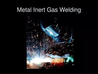
Gas Metal Arc Welding Is a process where a continuously fed metal electrode ( Wire ) contacts the base metal and produces heat . The arc is shielded by an inert gas
GMAW Components • DC or Direct Current power supply • Electrode or wire feed controller • Wire drive roller assembly • Shielding gas source (cylinder) & regulator • Manually held Gun & ground clamps • Wire reel
Gas Metal Arc Welding Principles • Gas metal arc welding is generally used due to the high efficiency of filler metal that can be deposited per hour. • GMAW is approximately 92% - 98% efficient • GMAW requires a shielding gas
Gas Metal Arc Welding Principles • The GMAW process is performed using DCEP ( Direct Current Electrode Positive) • Alternating current is never used for GMAW • DCEN is used only for a specialized process using emissive electrodes
GMAW Advantages • Welding can be done in all positions • No slag removal required • High efficiency • Less work piece distortion • Large gaps bridged easily , Good for poor fitup • High Weld Quality
Typical Setup for voltage • The GMAW machine is a “Constant Voltage” power supply. This is set using the voltage dial • This setting can be monitored by the “Volt” meter on the front panel of the welder • Ideal voltage settings can be found in the wire manufactures data book
Typical Setup for Wire speed • The wire feed rate or speed is set using the dial on the wire controller This setting increases or decreases current or “Heat”. This setting is measured in AMPS or IPM (inches per minute ) • Ideal settings can be monitored by the “Amp” meter on the front panel of the welder. Note : Some machines display “Current” (Same as AMPS) or IMP • Ideal settings can be found in the wire manufactures data book for both IPM and Current
Shielding Gas • Air in the welding zone is displaced by inert gas to “Shield” the molten weld pool and prevent it from contamination from Oxygen, Nitrogen and Water present in the atmosphere. • Insufficient gas flow will not displace the atmosphere resulting in “porosity” or voids in the deposited weld. • Flow is measured in CFH (Cubic Feet per Hour).
Insufficient Shielding Gas coverage • Gas not turned on • Flow rate not properly adjusted • Leaks in the hose supplying the shielding gas to the machine • GMAW / MIG Gun loose at wire drive connection • Spatter buildup on gas cup • Windy environment
Excessive Gas coverage • Will cause porosity. • The turbulence caused by the rapid flow of shielding gas exiting from the gas cup will draw the surrounding atmosphere into the stream of gas. • It will reduce weld pool temperatures causing decreased penetration .