Download
1 / 27
290 likes | 620 Views
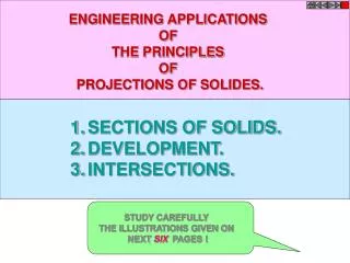
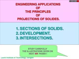
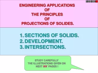
ENGINEERING APPLICATIONS OF THE PRINCIPLES OF PROJECTIONS OF SOLIDES. SECTIONS OF SOLIDS. DEVELOPMENT. INTERSECTIONS. STUDY CAREFULLY THE ILLUSTRATIONS GIVEN ON NEXT SIX PAGES !. OBSERVER. ASSUME UPPER PART REMOVED . SECTON PLANE IN FV. ASSUME LOWER PART REMOVED.

E N D
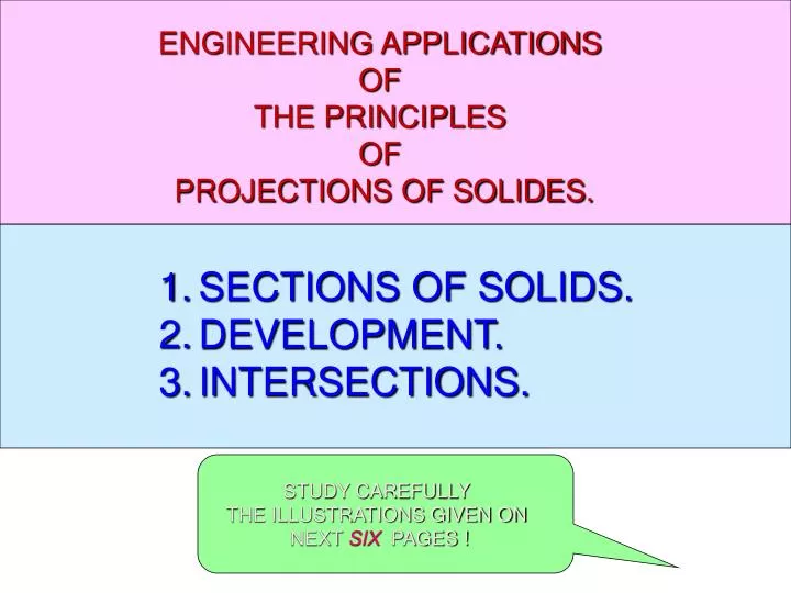
ENGINEERING APPLICATIONS OF THE PRINCIPLES OF PROJECTIONS OF SOLIDES. • SECTIONS OF SOLIDS. • DEVELOPMENT. • INTERSECTIONS. STUDY CAREFULLY THE ILLUSTRATIONS GIVEN ON NEXT SIX PAGES !
OBSERVER ASSUME UPPER PART REMOVED SECTON PLANE IN FV. ASSUME LOWER PART REMOVED SECTON PLANE IN TV. OBSERVER SECTIONING A SOLID. An object ( here a solid ) is cut by some imaginary cutting plane to understand internal details of that object. The action of cutting is called SECTIONING a solid & The plane of cutting is called SECTION PLANE. Two cutting actions means section planes are recommended. A) Section Plane perpendicular to Vp and inclined to Hp. ( This is a definition of an Aux. Inclined Plane i.e. A.I.P.) NOTE:- This section plane appears as a straight line in FV. B) Section Plane perpendicular to Hp and inclined to Vp. ( This is a definition of an Aux. Vertical Plane i.e. A.V.P.) NOTE:- This section plane appears as a straight line in TV. Remember:- 1. After launching a section plane either in FV or TV, the part towards observer is assumed to be removed. 2. As far as possible the smaller part is assumed to be removed. (A) (B)
For TV ILLUSTRATION SHOWING IMPORTANT TERMS IN SECTIONING. For True Shape SECTION PLANE TRUE SHAPE Of SECTION x y Apparent Shape of section SECTION LINES (450 to XY) SECTIONAL T.V.
Typical Section Planes & Typical Shapes Of Sections. Section Plane Through Generators Ellipse Triangle Section Plane Through Apex Parabola Section Plane Parallel to Axis. Section Plane Parallel to end generator. Hyperbola Ellipse Trapezium Cylinder through generators. Sq. Pyramid through all slant edges
DEVELOPMENT OF SURFACES OF SOLIDS. MEANING:- ASSUME OBJECT HOLLOW AND MADE-UP OF THIN SHEET. CUT OPEN IT FROM ONE SIDE AND UNFOLD THE SHEET COMPLETELY. THEN THE SHAPE OF THAT UNFOLDED SHEET IS CALLED DEVELOPMENT OF LATERLAL SUEFACES OF THAT OBJECT OR SOLID. LATERLAL SURFACE IS THE SURFACE EXCLUDING SOLID’S TOP & BASE. ENGINEERING APLICATION: THERE ARE SO MANY PRODUCTS OR OBJECTS WHICH ARE DIFFICULT TO MANUFACTURE BY CONVENTIONAL MANUFACTURING PROCESSES, BECAUSE OF THEIR SHAPES AND SIZES. THOSE ARE FABRICATED IN SHEET METAL INDUSTRY BY USING DEVELOPMENT TECHNIQUE. THERE IS A VAST RANGE OF SUCH OBJECTS. EXAMPLES:- Boiler Shells & chimneys, Pressure Vessels, Shovels, Trays, Boxes & Cartons, Feeding Hoppers, Large Pipe sections, Body & Parts of automotives, Ships, Aeroplanes and many more. WHAT IS OUR OBJECTIVE IN THIS TOPIC ? To learn methods of development of surfaces of different solids, their sections and frustums. 1. Development is different drawing than PROJECTIONS. 2. It is a shape showing AREA, means it’s a 2-D plain drawing. 3. Hence all dimensions of it must be TRUE dimensions. 4. As it is representing shape of an un-folded sheet, no edges can remain hidden And hence DOTTED LINES are never shown on development. But before going ahead, note following Important points. Study illustrations given on next page carefully.
Development of lateral surfaces of different solids. (Lateral surface is the surface excluding top & base) = H L D R + 3600 D L R=Base circle radius. L=Slant height. H S S S S Cylinder: A Rectangle Pyramids: (No.of triangles) Cone: (Sector of circle) L H= Height D= base diameter Prisms: No.of Rectangles L= Slant edge. S = Edge of base H= Height S = Edge of base Cube: Six Squares. Tetrahedron: Four Equilateral Triangles All sides equal in length
FRUSTUMS = R + 3600 L L L L1 L1 STUDY NEXT NINE PROBLEMS OF SECTIONS & DEVELOPMENT DEVELOPMENT OF FRUSTUM OF CONE DEVELOPMENT OF FRUSTUM OF SQUARE PYRAMID Base side Top side R= Base circle radius of cone L= Slant height of cone L1 = Slant height of cut part. L= Slant edge of pyramid L1 = Slant edge of cut part.
Problem 1: A pentagonal prism , 30 mm base side & 50 mm axis is standing on Hp on it’s base whose one side is perpendicular to Vp. It is cut by a section plane 450 inclined to Hp, through mid point of axis. Draw Fv, sec.Tv & sec. Side view. Also draw true shape of section and Development of surface of remaining solid. Solution Steps:for sectional views: Draw three views of standing prism. Locate sec.plane in Fv as described. Project points where edges are getting Cut on Tv & Sv as shown in illustration. Join those points in sequence and show Section lines in it. Make remaining part of solid dark. C B D Y1 A A B C D E A E d” c” X1 b” e” a” e d For True Shape: Draw x1y1 // to sec. plane Draw projectors on it from cut points. Mark distances of points of Sectioned part from Tv, on above projectors from x1y1 and join in sequence. Draw section lines in it. It is required true shape. a For Development: Draw development of entire solid. Name from cut-open edge I.e. A. in sequence as shown. Mark the cut points on respective edges. Join them in sequence in st. lines. Make existing parts dev.dark. c b TRUE SHAPE a’ b’ e’ c’ d’ X Y DEVELOPMENT
Problem 2: A cone, 50 mm base diameter and 70 mm axis is standing on it’s base on Hp. It cut by a section plane 450 inclined to Hp through base end of end generator.Draw projections, sectional views, true shape of section and development of surfaces of remaining solid. Solution Steps:for sectional views: Draw three views of standing cone. Locate sec.plane in Fv as described. Project points where generators are getting Cut on Tv & Sv as shown in illustration.Join those points in sequence and show Section lines in it. Make remaining part of solid dark. Y1 X1 e’ a’ h’ b’ c’ g’ f’ d’ g h f For True Shape: Draw x1y1 // to sec. plane Draw projectors on it from cut points. Mark distances of points of Sectioned part from Tv, on above projectors from x1y1 and join in sequence. Draw section lines in it. It is required true shape. a e For Development: Draw development of entire solid. Name from cut-open edge i.e. A. in sequence as shown.Mark the cut points on respective edges. Join them in sequence in curvature. Make existing parts dev.dark. b d c TRUE SHAPE OF SECTION A SECTIONAL S.V B o’ SECTION PLANE DEVELOPMENT C D E X Y g” h”f” a”e” b”d” c” F G H A SECTIONAL T.V
Problem 3: A cone 40mm diameter and 50 mm axis is resting on one generator on Hp( lying on Hp) which is // to Vp.. Draw it’s projections.It is cut by a horizontal section plane through it’s base center. Draw sectional TV, development of the surface of the remaining part of cone. A B C a’ e’ c’g’ h’b’ d’f’ D a’ h’ b’ c’ g’ f’ e’ d’ E g1 g h f1 h1 F f G a e1 a1 o1 e O H b1 d1 b d A c c1 Follow similar solution steps for Sec.views - True shape – Development as per previous problem! DEVELOPMENT o’ HORIZONTAL SECTION PLANE Y X o’ O SECTIONAL T.V (SHOWING TRUE SHAPE OF SECTION)
Problem 4: A hexagonal prism. 30 mm base side & 55 mm axis is lying on Hp on it’s rect.face with axis // to Vp. It is cut by a section plane normal to Hp and 300 inclined to Vp bisecting axis. Draw sec. Views, true shape & development. c’ f’ Note the steps to locate Points 1, 2 , 5, 6 in sec.Fv: Those are transferred to 1st TV, then to 1st Fv and Then on 2nd Fv. e’ c’ a’ d’ f’ b’ e’ a’ d’ b’ 8 3 7 4 6 5 1 2 Use similar steps for sec.views & true shape. NOTE: for development, always cut open object from From an edge in the boundary of the view in which sec.plane appears as a line. Here it is Tv and in boundary, there is c1 edge.Hence it is opened from c and named C,D,E,F,A,B,C. 5 6 2 1 X Y 4 3 8 7 f f1 e1 a1 e a d1 b1 d b c1 c X1 B A C F E D C Y1 SECTIONAL F.V. A.V.P300 inclined to Vp Through mid-point of axis. 1,2 3,8 4,7 5,6 AS SECTION PLANE IS IN T.V., CUT OPEN FROM BOUNDRY EDGE C1 FOR DEVELOPMENT. TRUE SHAPE OF SECTION DEVELOPMENT
Problem 5:A solid composed of a half-cone and half- hexagonal pyramid is shown in figure.It is cut by a section plane 450 inclined to Hp, passing through mid-point of axis.Draw F.v., sectional T.v.,true shape of section and development of remaining part of the solid. ( take radius of cone and each side of hexagon 30mm long and axis 70mm.) 3 2 4 Y1 5 1 Note: Fv & TV 8f two solids sandwiched Section lines style in both: Development of half cone & half pyramid: 6 A B 7 4’ C 3’ 5’ X1 2 4 2’ 3 6’ D 1 1’ E 7’ X Y O a’ c’f’ g’b’ d’e’ f 7 F g 6 e 5 G 4 5 6 7 4 A a 1 3 d 2 b c TRUE SHAPE O’ DEVELOPMENT F.V. SECTIONAL TOP VIEW.
TO DRAW PRINCIPAL VIEWS FROM GIVEN DEVELOPMENT. Problem 6: Draw a semicircle 0f 100 mm diameter and inscribe in it a largest circle.If the semicircle is development of a cone and inscribed circle is some curve on it, then draw the projections of cone showing that curve. = 4 E 5 3 R + 3600 D F L R=Base circle radius. L=Slant height. 1’ C G L 6 2 7’ 6’ 2’ B H 1 7 5’ 3’ 4’ X Y A g L A O 6 Solution Steps: Draw semicircle of given diameter, divide it in 8 Parts and inscribe in it a largest circle as shown.Name intersecting points 1, 2, 3 etc. Semicircle being dev.of a cone it’s radius is slant height of cone.( L ) Then using above formula find R of base of cone. Using this data draw Fv & Tv of cone and form 8 generators and name. Take o -1 distance from dev.,mark on TL i.e.o’a’ on Fv & bring on o’b’ and name 1’ Similarly locate all points on Fv. Then project all on Tv on respective generators and join by smooth curve. h f 5 a 7 o e 4 1 g’ a’ b d h’ b’ c’ d’f’ e’ 3 2 c o’
TO DRAW PRINCIPAL VIEWS FROM GIVEN DEVELOPMENT. Problem 7:Draw a semicircle 0f 100 mm diameter and inscribe in it a largest rhombus.If the semicircle is development of a cone and rhombus is some curve on it, then draw the projections of cone showing that curve. = Solution Steps: Similar to previous Problem: E R + 3600 D F L R=Base circle radius. L=Slant height. C G B H 6’ 2’ 3’ 5’ a’ h’ b’ c’ g’ f’ d’ e’ Y X 1’ 7’ 4’ A g A O L 7 6 h f 5 a e 4 b 3 d 2 1 c o’ 1 2 3 4 5 6 7
Problem 8: A half cone of 50 mm base diameter, 70 mm axis, is standing on it’s half base on HP with it’s flat face parallel and nearer to VP.An inextensible string is wound round it’s surface from one point of base circle and brought back to the same point.If the string is of shortest length, find it and show it on the projections of the cone. TO DRAW A CURVE ON PRINCIPAL VIEWS FROM DEVELOPMENT. o’ A Concept: A string wound from a point up to the same Point, of shortest length Must appear st. line on it’s Development. Solution steps: Hence draw development, Name it as usual and join A to A This is shortest Length of that string. Further steps are as usual. On dev. Name the points of Intersections of this line with Different generators.Bring Those on Fv & Tv and join by smooth curves. Draw 4’ a’ part of string dotted As it is on back side of cone. B C 1 D 3’ 2’ 2 4’ 1’ 3 E 4 X Y a’ c’ d’ e’ O b’ e a o 4 3 1 2 b d c A
Problem 9: A particle which is initially on base circle of a cone, standing on Hp, moves upwards and reaches apex in one complete turn around the cone. Draw it’s path on projections of cone as well as on it’s development. Take base circle diameter 50 mm and axis 70 mm long. It’s a construction of curve Helix of one turn on cone: Draw Fv & Tv & dev.as usual On all form generators & name. Construction of curve Helix:: Show 8 generators on both views Divide axis also in same parts. Draw horizontal lines from those points on both end generators. 1’ is a point where first horizontal Line & gen. b’o’ intersect. 2’ is a point where second horiz. Line & gen. c’o’ intersect. In this way locate all points on Fv. Project all on Tv.Join in curvature. For Development: Then taking each points true Distance From resp.generator from apex, Mark on development & join. 7’ HELIX CURVE 6’ A 5’ 4’ B 3’ 1 2’ C 1’ 2 a’ h’ b’ c’ g’ f’ e’ d’ D g 3 O 4 h E f 7 5 6 6 5 7 F a e O 4 G 3 1 b d 2 H c A o’ DEVELOPMENT X Y
INTERPENETRATION OF SOLIDS WHEN ONE SOLID PENETRATES ANOTHER SOLID THEN THEIR SURFACES INTERSECT AND AT THE JUNCTION OF INTERSECTION A TYPICAL CURVE IS FORMED, WHICH REMAINS COMMON TO BOTH SOLIDS. THIS CURVE IS CALLED CURVE OF INTERSECTION AND IT IS A RESULT OF INTERPENETRATION OF SOLIDS. PURPOSE OF DRAWING THESE CURVES:- WHEN TWO OBJECTS ARE TO BE JOINED TOGATHER, MAXIMUM SURFACE CONTACT BETWEEN BOTH BECOMES A BASIC REQUIREMENT FOR STRONGEST & LEAK-PROOF JOINT. Curves of Intersections being common to both Intersecting solids, show exact & maximum surface contact of both solids. Study Following Illustrations Carefully. Minimum Surface Contact. ( Point Contact) (Maximum Surface Contact) Lines of Intersections. Curves of Intersections. Square Pipes. Circular Pipes. Circular Pipes. Square Pipes.
SOME ACTUAL OBJECTS ARE SHOWN, SHOWING CURVES OF INTERSECTIONS. BY WHITE ARROWS. A machine component having two intersecting cylindrical surfaces with the axis at acute angle to each other. Intersection of a Cylindrical main and Branch Pipe. An Industrial Dust collector. Intersection of two cylinders. Pump lid having shape of a hexagonal Prism and Hemi-sphere intersecting each other. Two Cylindrical surfaces. A Feeding Hopper In industry. Forged End of a Connecting Rod.
FOLLOWING CASES ARE SOLVED. REFFER ILLUSTRATIONS AND NOTE THE COMMON CONSTRUCTION FOR ALL COMMON SOLUTION STEPS One solid will be standing on HP Other will penetrate horizontally. Draw three views of standing solid. Name views as per the illustrations. Beginning with side view draw three Views of penetrating solids also. On it’s S.V. mark number of points And name those(either letters or nos.) The points which are on standard generators or edges of standing solid, ( in S.V.) can be marked on respective generators in Fv and Tv. And other points from SV should be brought to Tv first and then projecting upward To Fv. Dark and dotted line’s decision should be taken by observing side view from it’s right side as shown by arrow. Accordingly those should be joined by curvature or straight lines. Note: Incase cone is penetrating solid Side view is not necessary. Similarly in case of penetration from top it is not required. 1.CYLINDER TO CYLINDER2. 2.SQ.PRISM TO CYLINDER 3.CONE TO CYLINDER 4.TRIANGULAR PRISM TO CYLNDER 5.SQ.PRISM TO SQ.PRISM 6.SQ.PRISM TO SQ.PRISM ( SKEW POSITION) 7.SQARE PRISM TO CONE ( from top ) 8.CYLINDER TO CONE
CASE 1. CYLINDER STANDING & CYLINDER PENETRATING 2’ 1” 3” 4’ 2” 3’ 1’ 4” a’ a” h” b” b ’h’ g” c” c’g’ d” d’f’ f” a’ e” 4 3 1 2 Problem:A cylinder 50mm dia.and 70mm axis is completely penetrated by another of 40 mm dia.and 70 mm axis horizontally Both axes intersect & bisect each other. Draw projections showing curves of intersections. X Y
2’ 1” 4’ 3” 2” 3’ 4” 1’ a’ a’ a” d” b’ b’ b” d’ d’ c’ c’ c” 4 3 1 2 CASE 2. CYLINDER STANDING & SQ.PRISM PENETRATING Problem:A cylinder 50mm dia.and 70mm axis is completely penetrated by a square prism of 25 mm sides.and 70 mm axis, horizontally. Both axes Intersect & bisect each other. All faces of prism are equally inclined to Hp. Draw projections showing curves of intersections. X Y
CASE 3. CYLINDER STANDING & CONE PENETRATING 1 7’ 2 8 6’ 8’ 3 7 1’ 5’ 4 6 2’ 4’ 5 3’ Problem: A cylinder of 80 mm diameter and 100 mm axis is completely penetrated by a cone of 80 mm diameter and 120 mm long axis horizontally.Both axes intersect & bisect each other. Draw projections showing curve of intersections. X Y
1” 2’ 4’ 3” 2” 3’ 1’ 4” a’ a’ a” d” b’ b’ b” d’ d’ c’ c’ c” 4 3 1 2 Problem:A sq.prism 30 mm base sides.and 70mm axis is completely penetrated by another square prism of 25 mm sides.and 70 mm axis, horizontally. Both axes Intersects & bisect each other. All faces of prisms are equally inclined to Vp. Draw projections showing curves of intersections. CASE 4. SQ.PRISM STANDING & SQ.PRISM PENETRATING X Y
a a a 2’ 1” 4’ 3” 2” 3’ 4” 1’ b b c c d d e e f f f X Y 4 3 1 2 Problem:A cylinder 50mm dia.and 70mm axis is completely penetrated by a triangular prism of 45 mm sides.and 70 mm axis, horizontally. One flat face of prism is parallel to Vp and Contains axis of cylinder. Draw projections showing curves of intersections. CASE 5. CYLINDER STANDING & TRIANGULAR PRISM PENETRATING b e
CASE 6. SQ.PRISM STANDING & SQ.PRISM PENETRATING (300 SKEW POSITION) 1” 2’ 4’ 3” 3’ 2” 4” 1’ a” f” e” b” c” d” 4 3 1 2 Problem:A sq.prism 30 mm base sides.and 70mm axis is completely penetrated by another square prism of 25 mm side s.and 70 mm axis, horizontally. Both axes Intersect & bisect each other.Two faces of penetrating prism are 300 inclined to Hp. Draw projections showing curves of intersections. a’ f’ e’ b’ c’ d’ X 300 Y
2’ 1’ 3’ 5’ 4’ 6’ g h f 8 a 9 7 e 10 6 1 b d 2 c 5 3 4 5 mm OFF-SET CASE 7. CONE STANDING & SQ.PRISM PENETRATING (BOTH AXES VERTICAL) X Y a’ b’h’ c’g’ d’f’ e’ Problem: A cone70 mm base diameter and 90 mm axis is completely penetrated by a square prism from top with it’s axis // to cone’s axis and 5 mm away from it. a vertical plane containing both axes is parallel to Vp. Take all faces of sq.prism equally inclined to Vp. Base Side of prism is 0 mm and axis is 100 mm long. Draw projections showing curves of intersections.
Problem: A vertical cone, base diameter 75 mm and axis 100 mm long, is completely penetrated by a cylinder of 45 mm diameter. The axis of the cylinder is parallel to Hp and Vp and intersects axis of the cone at a point 28 mm above the base. Draw projections showing curves of intersection. 1 1 1 2 2 8, 8 2 3 7 3 3 7, 4 4 6 4 6 5 5 5 Y X g h f a e b d c CASE 8. CONE STANDING & CYLINDER PENETRATING o’ o” a’ b’h’ c’g’ d’f’ e’ g” g”h” a”e” b”d” c”