Download
1 / 11
731 likes | 1.42k Views
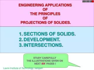
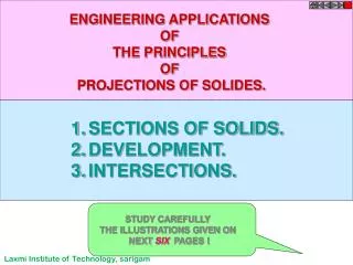
SECTIONS OF SOLIDS Part I. Prof.T.JEYAPOOVAN Department of Mechanical Engineering Hindustan Institute of Technology and Science Chennai-603103, India. SECTION OF A SOLID.

E N D
SECTIONS OF SOLIDS Part I Prof.T.JEYAPOOVAN Department of Mechanical Engineering Hindustan Institute of Technology and Science Chennai-603103, India www.EGlive.in
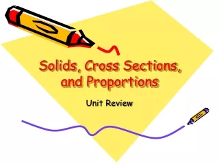
SECTION OF A SOLID • When a plane cuts a solid, the cut portion is removed and the section with new corners are obtained on the sides or edges of the solid. • These points are connected in the projections and joined in proper sequence to show the section in that view. • The cutting plane is same as the one discussed in Projections of Planes and are represented by their traces. www.EGlive.in
To draw Sections • Draw the projections of the solid, then draw the trace of the cutting plane. Carefully mark the new corners on the edges cut by the cutting plane, then project them to the other view. • Cutting plane will be in one of the following positions • inclined to HP and perpendicular to VP • inclined to VP and perpendicular to HP • perpendicular to both HP and VP • perpendicular to HP and parallel to VP • perpendicular to VP and parallel to HP www.EGlive.in
Example 1: A square prism of base side 30 mm and axis length 60 mm is resting on HP on one of its bases, with a base side inclined at 25° to VP. It is cut by a plane inclined at 40° to HP and perpendicular to VP and is bisecting the axis of the prism. Draw its front view, sectional top view and true shape of section. • Draw the TV and project the FV of the prism. Draw the trace of the cutting plane at 40º to XY. • Mark the new corners in FV and project them to TV to get apparent section. • Draw new reference line X1Y1 and use the distance of new corners in TV from XY and mark from X1Y1 , then join them to get the true shape of section. www.EGlive.in
Example 2: A square pyramid of base side 30 mm and axis length 60 mm is resting on HP on its base with one side of base inclined at 30° to VP. It is cut by a plane inclined at 45° to HP and perpendicular to VP and passes through the axis at a distance 25 mm from the apex. Draw its front view, sectional top view and true shape of the section. • Draw the TV and project the FV of the pyramid. Draw the trace of the cutting plane at 45º to XY. • Mark the new corners in FV and project them to TV to get apparent section. • Draw new reference line X1Y1 and use the distance of new corners in TV from XY and mark from X1Y1 , then join them to get the true shape of section. www.EGlive.in
Example 3: A cylinder of base diameter 40 mm and axis length 55 mm is resting on HP on its base. It is cut by a plane inclined at 45° to HP and perpendicular to VP. The plane is passing through a point on the circumference of the top base. Draw its front view, sectional top view, and true shape of section. • Draw TV and project FV of the cylinder. Draw the trace of cutting plane at 45º to XY. • Mark the new corners in FV, then project them to TV to get apparent section. • Draw new reference line X1Y1 and use the distance of new corners in TV from XY and mark from X1Y1 , then join them to get true shape of section as an ellipse. www.EGlive.in
Example 4: A cone of base diameter 65 mm and axis length 75 mm, resting on HP on its base is cut by a plane inclined at 45° to HP and perpendicular to VP, passing through a point 35 mm below the apex. Draw the front view and sectional top view and true shape of this section. • Draw TV and project FV of the cone. Draw the trace of the cutting plane at 45º to XY. • Mark the new corners in FV and project them to TV to get apparent section. • Draw new reference line X1Y1 and use the distance of new corners in TV from XY and mark from X1Y1 , then join them to get the true shape of section as an ellipse. www.EGlive.in
Example 5: A square prism of base side 45 mm and axis length 90 mm, stands on the HP with its axis vertical, such that its faces are equally inclined to the VP. The prism is cut by a plane, perpendicular to VP inclined at 60º to the HP and passing through the point on the axis of the prism 65 mm above HP. Draw its front view, sectional top view and true shape of section. • Draw the TV and project FV of the prism. Draw trace of the cutting plane at 60º to XY. • Mark the new corners in FV and project them to TV. • Draw new reference line X1Y1 and use the distance of new corners in TV from XY and mark from X1Y1 , then join them to get the true shape of section. www.EGlive.in
Tips to draw Sections • Draw the projections of the solid, then draw the trace of the cutting plane. Carefully mark the new corners on the edges cut by the cutting plane, then project them to the other view. • When a solid is resting on HP on its base and the cutting plane passes through a base in front view, then two points will be obtained on that base, the point in the front and behind are coinciding and are marked clearly in top view. www.EGlive.in
REFERENCE BOOKS Jeyapoovan T, “Lesson Plans for Engineering Graphics”, 2010, Vikas Publishing House Pvt Ltd, New Delhi. Jeyapoovan T, “Engineering Drawing and Graphics”, 2011, Vikas Publishing House Pvt Ltd, New Delhi. www.EGlive.in
End of Lesson 7 Thank You www.EGlive.in