Download
1 / 19
330 likes | 1.08k Views
Actuators & Directional Control Valves. HYDRAULICS – MODULE 2. Objectives. Identify the types of Hydraulic Actuators. Identify the symbols of Actuators. Identify the functions of Actuators. Identify the types of directional control valves.

E N D
Actuators & Directional Control Valves HYDRAULICS – MODULE 2
Objectives • Identify the types of Hydraulic Actuators. • Identify the symbols of Actuators. • Identify the functions of Actuators. • Identify the types of directional control valves. • Identify the function of directional control valves. • Identify the function of the shut off valve. • Draw a basic hydraulic circuit diagram. • Simulate the circuit diagram using FluidSim software. • Assemble the circuit practically and check its operation.
Single Acting Cylinder • The single acting cylinder, is used to convert hydraulic energy into mechanical energy (to give a linear force in one direction). • Forward stroke is achieved by hydraulic pressure. • Return stroke is achieved by the effect of the gravity or the load.
Double Acting Cylinder • The double acting cylinder, is used to convert hydraulic energy into mechanical energy in two directions. • It produces a linear force in two directions. • Forward and backward strokes are achieved by the hydraulic pressure VIDEO
Hydraulic Motor • Hydraulic Motor is used to convert hydraulic energy into mechanical energy. • It generates rotary movement in either one direction or two directions (rotary actuator). • The motor rotates because of the flow passing through it. When the direction of flow is changed, the direction of rotation changes as well.
Hydraulic Cylinder Forces • Hydraulic cylinders transfer fluid pressure into mechanical motion. The force of this motion depends on if the cylinder rod is EXTENDING or RETRACTING. • A cylinder's extension force is greater than its retraction force because pressurized hydraulic fluid pushes on the entire surface of the piston to extend it. • The generated force in the hydraulic cylinder is calculated by the following formula: Force (N) Area (m2) Pressure (N/m2)
Extension force (Fe): • During the forward stroke the effective piston area is (A) and the produced force is (Fe). • During the backward (retraction) stroke the effective piston area is (A- a) (a is the piston rod area ,the produced force is (Fr) • From the above equations, it is obvious that the extension force (Fe) is greater than the retraction force (Fr).
Example • 1) Fe = P x A • P = 20 x 100000 Pa • Fe = 2000000 x 0.15 • Fe = 300000 N = 300 kN • 2) Fr = P(A-a) • P = 20 x 100000 Pa • Fr = 2000000 x (0.15 – 0.08) • Fr = 2000000 x 0.07 • Fr = 140000 N = 140kN • Calculate the forces (Fe) and (Fr) in the Figure below if you are given the following: • A= 0.15 m2 • a= 0.08 m2 • P= 20 bar
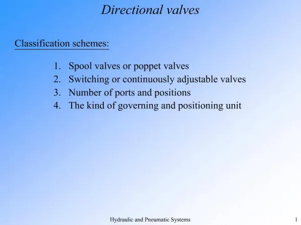
Directional Control Valves • They perform three functions: a) Open b) Close c) Change the flow paths to control the direction of motion of actuators. They are classified according to the number of ports and positions such as follows
4/2 way valve 4/2 stands for 4 PORTS and 2 POSITIONS (A) and (B) are working ports (P) is the Pressure Port (T) is the Tank Port • It is actuated manually (lever) and returned by a spring. • Normal position: flow from P to A and from B to T. • Actuated position: flow from P to B and from A to T. Show FluidSim
4/3way valve 4/3 stands for 4 PORTS and 3 POSITIONS (A) and (B) are working ports (P) is the Pressure Port (T) is the Tank Port • Normal position: Ports A and B are blocked. Port P is connected to tank (T) • It is manually actuated.
Shut off Valve • The shutoff valve is a manually opened or closed valve.
Practical Task 1 Prepare the components Connect the hoses Check that all parts are connected properly. Operating pressure should not exceed 20 bar. Switch on the electrical supply then the hydraulic power pack. Start the circuit Switch off the circuit Dismantle and tidy up. Use the Fluidsim software to simulate the circuit.
Practical Task 2 • A furnace door is to be opened and closed by a double-acting cylinder. The cylinder is activated by a hydraulic valve with spring return. This ensures that the door opens only as long as the valve is actuated. When the valve actuating lever is released, the door closes again
Solution Description • Once the circuit has been assembled and checked. The hydraulic power pack should be switched on and the system pressure set on the pressure relief valve to 20 bar. Pressure gauges should be used to measure the pressure. • When the hand lever of the 4/2 way valve is actuated, the piston rod of the cylinder will advance until the lever is released. The piston rod will immediately return to its retracted end position. Before the pressures and times are measured, the piston rod should be advanced and retracted several times to expel any air which may have entered the piston-rod chamber during the previous exercises.
Class Activity: Solve the Worksheet at the end of the Module