Download
1 / 17
170 likes | 324 Views
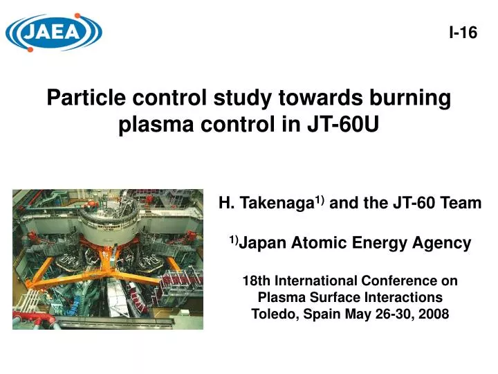
I-16. Particle control study towards burning plasma control in JT-60U. H. Takenaga 1) and the JT-60 Team 1) Japan Atomic Energy Agency 18th International Conference on Plasma Surface Interactions Toledo, Spain May 26-30, 2008. JT-60U.

E N D
I-16 Particle control study towards burning plasma control in JT-60U H. Takenaga1) and the JT-60 Team 1)Japan Atomic Energy Agency 18th International Conference on Plasma Surface Interactions Toledo, Spain May 26-30, 2008
JT-60U ITER : Ip=15 MA, BT=5.3 T, R=6.2 m, a=2 m, Fixed n&T profiles Ti(0)=10-25 keV Ti(0)=25 keV (b) HH98(y,2)=1.2 (a) Ti(0)=20 keV (b) (a) HH98(y,2)=1.0 HH98(y,2)=1.0 Ti(0)=15 keV HH98(y,2)=0.8 Ti(0)=10 keV PEX=40 MW Introduction • Particle control plays a key role in burning plasmas. • particle/impurity transport, fuelling, pumping, etc.. n(r)&T(r) PEX • Transport • MHD … P Fuelling j(r), V(t), … Wall pumping Divertor pumping It is important to establish effective particle control for both increase and decrease in QDT towards first burning plasma experiments in ITER.
JT-60U Outline • Controllability of density profiles and effects of density profiles on impurity transport. • Controllability of confinement and pedestal using edge fuelling. • Controllability of edge density using divertor pumping. • Burning plasma simulation experiments.
JT-60U Controllability of density profiles and effects of density profiles on impurity transport. • Density profiles have large impacts on fusion output and impurity accumulation. Peaked density profile • High fusion output with low edge density • High impurity accumulation level ? • Flat density profile • High edge density for high fusion output • Low impurity accumulation level ? • ITG/TEM turbulence theoryhas predicted peaked density profile formed by anomalous inward pinch and italso indicated that density peaking decreases with increasing effective collisionality (eff=ei/De). • Deis the curvature drift frequency, which provides an estimate of the growth rate of the most unstable mode for ITG and TEM. • It is important for establishment of an effective particle control scenario to understand mechanisms for regulating the density profile.
JT-60U Collisionality dependence of density peaking is consistent with ITG/TEM turbulence theory. ELMy H-mode plasmas ELMy H-mode plasmas <ne>=3.4x10¹⁹ m-3 Ip=1.0 MA, BT=2-2.1T, PNB=8-10 MW <ne>=1.5x10¹⁹ m-3 ITER @ r/a=0.5 • The density profile is more peaked in low density plasmas than in high density plasmas. • The density peaking factor decreases with increasing effective collisionality. • Note that density peaking factor used here is not affected by the edge boundary condition when particle source is zero ( n/n=v/D).
JT-60U Density peaking factor increases with ctr-rotation. Large vol. configuration ctr ctr co bal co co ctr • P-NB perp.: 7 units • co: 2 units • ctr: 2 units @ r/a=0.2 • Perp. NB power scan with co-, bal- and ctr-injection. • E// is larger in the ctr-case than in the co-case. However, Ware pinch velocity (~0.02 m/s@r/a=0.3) is one order of magnitude lower than particle source induced flux velocity (/n). • Small Ware pinch contribution to determination of density profile.
JT-60U Carbon density is relatively flat in all cases. ELMy H-mode plasmas eff=0.24 ctr bal co eff=1.8 @ r/a=0.5 @ r/a=0.2 • Carbon density measured using CXRS has a flat or slightly hollow profile, although neoclassical transport theory predicts inward pinch velocity. • No clear dependence of carbon density profiles on effective collisionality and toroidal rotation. • No concern of light impurity accumulation even with peaked density profile in ELMy H-mode plasmas.
JT-60U Tungsten is accumulated with peaked density profile. Large vol. configuration FSTs ctr ctr bal bal co co • The Ferritic Steel Tiles (FSTs) have ingredient of 8%Cr, 2%W and 0.2%V and cover ~10% of the surface. • Large tungsten radiation from the core plasma (IW+44) is observed with ctr-NB injection even at given orbit loss power, which could be correlated with tungsten source. • Heavy impurity accumulation is one of the large concerns with peaked density profile in ELMy H-mode plasmas.
JT-60U Controllability of confinement and pedestal using edge fuelling. • HFS shallow pellet injections can sustain high confinement at high density, while gas-puffing reduces confinement. Possibility of flexible control using combined fuelling. • However, plasma responses to gas-puffing could be slower and huge amount of gas-puffing is necessary. • In order to improve controllability, supersonic molecular beam injection (SMBI) has been installed in collaboration with CEA-Cadarache. Frequency : <10 Hz, Duration : ~2 ms /pulse, Gas flow : ~1.2 Pam3/pulse at PBK=6 bar (measured), Speed : 2.2 km/s at T=150oC and PBK=5 bar (calculation)
JT-60U 8 7 6 5 4 3 2 1 0 4.35 4.4 4.45 4.5 Quick decrease in ion temperature is observed at r/a~0.8 by SMBI. r/a 0.18 HFS LFS 0.21 (keV) 0.29 0.35 i T 0.41 0.56 0.72 0.81 dt=0.167ms 0.90 Divertor Time (s) • Density jump can be seen after SMBI pulse as similar as pellet injection. • SMBI could directly affect the plasma parameters at r/a~0.8, although light from SMBI mainly emitted outside the separatrix. dt=1ms • The SMBI speed estimated from the fast TV camera is slower than the calculation. Ionization front could move slowly towards plasma boundary.
JT-60U Confinement degrades at high density with constant pedestal pressure in the case of SMBI. • Confinement degrades with SMBI, while it is kept constant with HFS shallow pellets, indicating flexible control using combined fuelling. • The penetration position of the pellet was estimated to be r/a=0.77-0.84, which is inside the pedestal top. • Pedestal pressure is almost constant in the case of SMBI, which is similar as in the case of gas-puffing. Pedestal pressure is enhanced in the case of pellet injection.
JT-60U Controllability of edge density using divertor pumping. Divertor pump off on E045331 • Dynamic plasma-wall interaction • Increase in degree of self-regulation • Slower response 20 4 ne (1019 m-3) PNB (MW) MARFE 10 0 0 1 ID (1023 s-1) 0 1 Div (1022 s-1) Dynamic model is required in addition to static model. 0 Wall -1 15 20 25 30 Time (s) • Wall saturation and even outgas from the wall have been observed in the long pulse discharges in JT-60U. • Behavior of wall retention can not be understood using simple static model. • Outgas from the wall increases just after divertor pump on.
JT-60U Simulations using the UEDGE code. • Recycling coefficient • Static wall retention • Rst=0.995 • Dynamic wall retention • Rdy=CQ(Q/Q0-1)+C(0/-1) • Divertor pump • Rpump=-0.02(1-exp(-t/0.25)) • Total • Rtot=Rst+Rdy+Rpump QBC=6.5 MW BC=7.5x10²⁰ /s i=e=1.0 m2/s D=0.25 m2/s Rdy is assumed to increase with increasing heat flux and decreasing particle flux. R is determined by the balance among reflection, trapping (potential and chemical), thermal desorption, and sputtering (physical and chemical).
JT-60U Dynamic plasma-wall interaction slows plasma responses to the divertor pumping. • CQ=0.08exp(-t/1.0) • +0.02exp(-t/100), • C=0.4CQ Rdy=CQ(Q/Q0-1)+C(0/-1) CQ=C=0 CQ=0.1, C=0.4CQ Divertor pumping Total pumping Wall pumping • Time dependent CQ and C are required for reproducing the experiment. • This result indicates that wall retention depends on wall condition, i.e. amount of wall retention.
JT-60U P P-simulation Burning plasma simulation experiments. NB system Real time measurement This linkage is experimentally simulated in JT-60U. particle heating simulation : P~ne2Ti2 ne & Ti n(r)&T(r) Group A PEX • Transport • MHD … Group B External heating simulation : PEX Fuelling j(r), V(t), … Wdia SMBI • Burning plasma simulation scheme has been developed using 2 groups of NB, where one simulates particle heating and the other simulates external heating. • Ti dependence of <v>DT in the range of Ti=10-25 keV is incorporated in the scheme as P~ne2Ti2.
JT-60U SMBI decreases simulated fusion gain due to confinement degradation and flattening of pressure profile. E048281 E048352 BPS BPS Wdia FB Wdia FB • SMBI ~7Pam3/s • 4atm, 10Hz, LFS
JT-60U Summary • Particle control study has been conducted to expand understanding of burning plasma controllability. • Peakedness of density profiles increases with decreasing collisionality, which is consistent with ITG/TEM turbulence theory. Other control parameters, such as toroidal rotation, exist. • Metal impurity accumulation is observed with peaked density profile, while light impurity accumulation is not. • Confinement degrades with SMBI, while it is kept constant with HFS shallow pellets, indicating flexible control using combined fuelling. • The UEDGE simulation suggests that dynamic plasma-wall interaction slows plasma responses to divertor pumping. • Using the burning plasma simulation scheme, it is demonstrated to reduce the simulated fusion gain with SMBI due to confinement degradation and flattening of pressure profile.