Download
1 / 37
400 likes | 560 Views
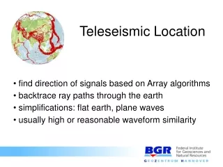
Coherence-weighted Wavepath Migration for Teleseismic Data. J. Sheng, G. T. Schuster, K. L. Pankow, J. C. Pechmann, and R. L. Nowack. University of Utah. Feb. 5, 2004. Motivation. Given: Teleseismic data. Goal: Local crustal structure. Solution I: Receiver function (RF). Principle of RF.

E N D
Coherence-weighted Wavepath Migration for Teleseismic Data J. Sheng, G. T. Schuster, K. L. Pankow, J. C. Pechmann, and R. L. Nowack University of Utah Feb. 5, 2004
Motivation Given: Teleseismic data Goal: Local crustal structure Solution I: Receiver function (RF)
Principle of RF Green’s fun. Instrument Source history Vertical Comp. Radial (Langston, 1977, 1979) P PS Moho P
pPs pSs pPp Moho Problems • Other phases generate artifacts
Motivation Given: teleseismic data Goal: local crustal structure Solution I: Receiver function (RF) Solution II: Xcorrelogram mig. (Xmig)
Principle of Xmig Ghost P-wave Direct P-wave
Problems • Incident angle usually > 30 deg. • Irregular spacing • Low frequency and long source • history
Motivation Given: teleseismic data Goal: local crustal structure Solution I: Receiver function (RF) Solution II: Xcorrelogram mig. (Xmig) Solution III: Coherence-weighted WM
Outline Coherence-weighted WM Synthetic Test Earthquake Data Summary
Coherence-weighted WM Step 1: Calculate radial and vertical RF • zero-phase traces b. source wavelet c. deconvolution
Step 1: Calculate radial and vertical RF Coherence-weighted WM Step 2: Migrate RF and obtain ps, pPs, and pPp images
P S X’ X’ X’ X X X Wavepath Migration R Plane wave Mps(x)=RRF(TS-TP) MpPs(x)=RRF(TS+TP) MpPp(x)=VRF(2TP)
Step 1: Calculate radial and vertical RF Step 2: Migrate RF and obtain ps, pPs, and pPp images Coherence-weighted WM Step 3: Coherence weight
Coherence-weighted WM ps pPs pPp 0 Depth (km) 60 0 220 0 220 0 220 Distances (km) Distances (km) Distances (km) 0 MCW=W*Mps Depth (km) 60 0 220 Distances (km)
Outline Coherence-weighted WM Synthetic Test Earthquake Data Summary
0 Depth (km) 60 0 Distances (km) 220 Synthetic Model
Parameters (Synthetic) • Plane P-wave incident at 40 deg. • 221 Stations with 1km spacing • Source peak frequency 0.6 Hz
Synthetic Seismogram 0 Traveltime (sec.) 70 Vertical Radial
Radial RF (Synthetic) 0 Traveltime (sec.) 20
Vertical RF (Synthetic) 0 Traveltime (sec.) 20
0 Depth (km) 60 0 220 Distances (km) ps Image (Synthetic)
0 Depth (km) 60 0 220 Distances (km) pPs Image (Synthetic)
0 Depth (km) 60 0 220 Distances (km) pPp Image (Synthetic)
0 Depth (km) 60 0 220 Distances (km) CW Image (Synthetic)
Outline Coherence-weighted WM Synthetic Test Earthquake Data Summary
Station Map 41.8 Great Salt Lake Latitude (deg.) 39.8 -113.5 -110.5 Longitude (deg.)
50 sec. 50 sec. 50 Processing Parameters 120 Time (sec.) Passband: 0.2~0.6 Hz 200 Water-level: 0.001 270
0 Time (sec.) 20 0 200 Distances (km) Radial RF
0 Time (sec.) 20 0 200 Distances (km) Vertical RF
0 Depth (km) 60 0 200 Distances (km) ps Image
0 Depth (km) 60 0 200 Distances (km) pPs Image
0 Depth (km) 60 0 200 Distances (km) pPp Image
0 Depth (km) 60 0 200 Distances (km) CW Image
Outline Coherence-weighted WM Synthetic Test Earthquake Data Summary
Summary • ps, pPs, and pPp arrivals in RF can be migrated • to provide a different perspective. • CWWM can combine three images to correctly • image the reflector with attenuated artifacts. • This method can image the Moho at the depth • consistent with previous studies.
Acknowledgment I thank the sponsors of the 2003 UTAM Consortium for their financial support .