Download
1 / 1
10 likes | 176 Views
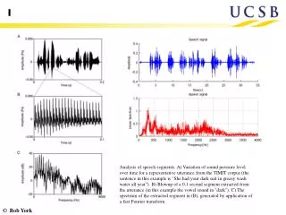
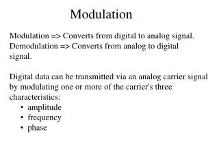
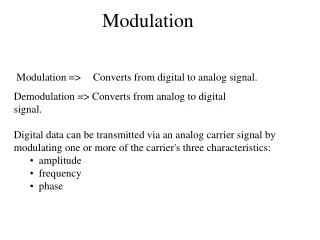
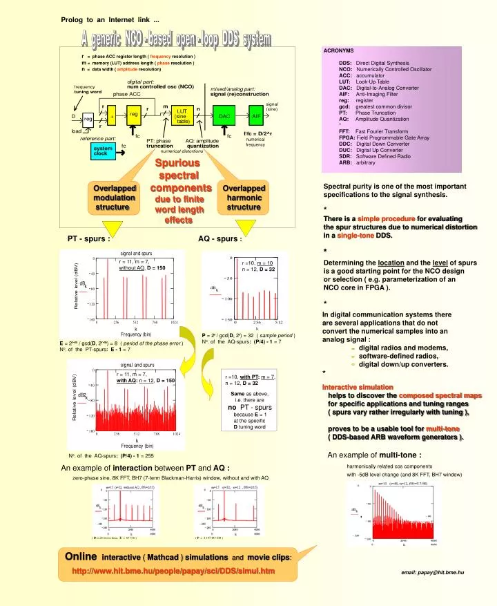
Prolog to an Internet link . A generic NCO - based open - loop DDS system. ACRONYMS DDS: Direct Digital Synthesis NCO: Numerically Controlled Oscillator ACC: accumulator LUT: Look-Up Table DAC: Digital-to-Analog Converter AIF: Anti-Imaging Filter

E N D
Prolog to an Internet link ... A generic NCO - based open - loop DDS system ACRONYMS DDS: Direct Digital Synthesis NCO: Numerically Controlled Oscillator ACC: accumulator LUT: Look-Up Table DAC: Digital-to-Analog Converter AIF: Anti-Imaging Filter reg: register gcd: greatest common divisor PT: Phase Truncation AQ: Amplitude Quantization * FFT: Fast Fourier Transform FPGA: Field Programmable Gate Array DDC: Digital Down Converter DUC: Digital Up Converter SDR: Software Defined Radio ARB: arbitrary r = phase ACC register length ( frequency resolution ) m = memory (LUT) address length ( phase resolution ) n = data width ( amplitude resolution) numerical frequency Spurious spectral components due to finite word length effects Spectral purity is one of the most important specifications to the signal synthesis. * Overlapped modulation structure Overlapped harmonic structure There is a simple procedure for evaluating the spur structures due to numerical distortion in a single-tone DDS. * PT - spurs : AQ - spurs : r = 11, m = 7, without AQ, D = 150 Determining the location and the level of spurs is a good starting point for the NCO design or selection ( e.g. parameterization of an NCO core in FPGA ). * r =10, m = 10 n = 12, D = 32 In digital communication systems there are several applications that do not convert the numerical samples into an analog signal : digital radios and modems, software-defined radios, digital down/up converters. * P = 2r/ gcd(D, 2r) = 32 ( sample period ) No. of the AQ-spurs:(P/4) - 1 = 7 E = 2r-m / gcd(D, 2r-m) = 8 ( period of the phase error ) No. of the PT-spurs: E - 1 = 7 r = 11, m = 7, with AQ:n = 12, D = 150 r =10, with PT:m = 7, n = 12, D = 32 Interactive simulation helps to discover the composed spectral maps for specific applications and tuning ranges ( spurs vary rather irregularly with tuning ), proves to be a usable tool for multi-tone ( DDS-based ARB waveform generators ). Same as above, i.e. there are no PT - spurs because E = 1 at the specific D tuning word An example of multi-tone: No. of the AQ-spurs:(P/4) - 1 = 255 An example of interaction between PT and AQ: harmonically related cos components with -5dB level change (and 8K FFT, BH7 window) zero-phase sine, 8K FFT, BH7 (7-term Blackman-Harris) window, without and with AQ ( D is all two in hexa, E = 65 536 ) ( P = 2 147 483 648 ) Onlineinteractive(Mathcad)simulations and movie clips: http://www.hit.bme.hu/people/papay/sci/DDS/simul.htm email: papay@hit.bme.hu