Download
1 / 23
230 likes | 366 Views
Pipelining and Exploiting Instruction-Level Parallelism (ILP). Pipelining and Instruction-Level Parallelism. Definition of basic instruction block Increasing Instruction-Level Parallelism (ILP) & Size of Basic Block: Using Loop Unrolling MIPS Loop Unrolling Example.

E N D
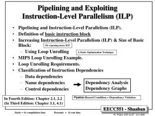
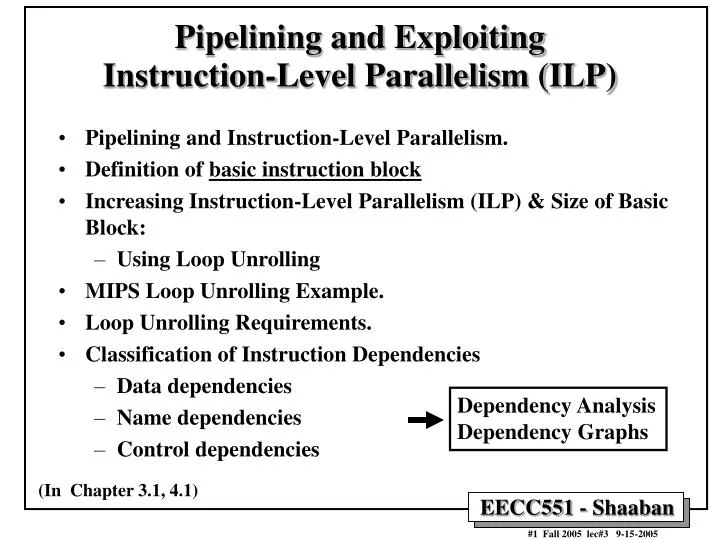
Pipelining and Exploiting Instruction-Level Parallelism (ILP) • Pipelining and Instruction-Level Parallelism. • Definition of basic instruction block • Increasing Instruction-Level Parallelism (ILP) & Size of Basic Block: • Using Loop Unrolling • MIPS Loop Unrolling Example. • Loop Unrolling Requirements. • Classification of Instruction Dependencies • Data dependencies • Name dependencies • Control dependencies Dependency Analysis Dependency Graphs (In Chapter 3.1, 4.1)
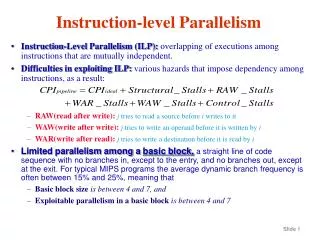
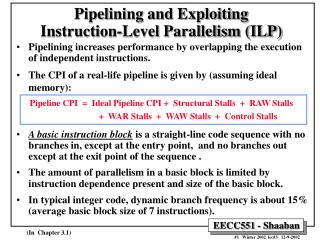
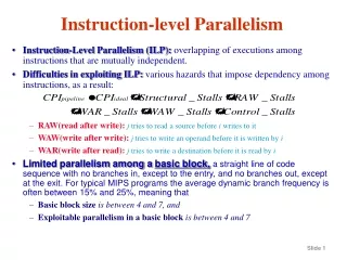
Pipelining and Exploiting Instruction-Level Parallelism (ILP) • Instruction-Level Parallelism (ILP) exists when instructions in a sequence are independent and thus can be executed in parallel by overlapping. • Pipelining increases performance by overlapping the execution of independent instructions and thus exploits ILP in the code. • Preventing instruction dependency violations (hazards) may result in stall cycles in a pipelined CPU increasing its CPI (reducing performance). • The CPI of a real-life pipeline is given by (assuming ideal memory): Pipeline CPI = Ideal Pipeline CPI + Structural Stalls + RAW Stalls + WAR Stalls + WAW Stalls + Control Stalls • Programs that have more ILP (fewer dependencies) tend to perform better on pipelined CPUs. • More ILP mean fewer instruction dependencies and thus fewer stall cycles needed to prevent instruction dependency violations (In Chapter 3.1)
Basic Instruction Block • A basic instruction block is a straight-line code sequence with no branches in, except at the entry point, and no branches out except at the exit point of the sequence. • Example: Body of a loop. • The amount of instruction-level parallelism (ILP) in a basic block is limited by instruction dependence present and size of the basic block. • In typical integer code, dynamic branch frequency is about 15% (resulting average basic block size of about 7 instructions). • Any static technique that increases the average size of basic blocks which increases the amount of ILP in the code and provide more instructions for static pipeline scheduling by the compiler possibly eliminating more stall cycles and thus improves pipelined CPU performance. • Loop unrolling is one such technique that we examine next Start of Basic Block End of Basic Block (In Chapter 3.1)
Static Program Order D J B I H L K E F G N M O C A . . . . . . Program Control Flow Graph (CFG) . . . . . . . . . . . . NT = Branch Not Taken T = Branch Taken . . . Basic Blocks/Dynamic Execution Sequence (Trace) Example • A-O = Basic Blocks terminating with conditional branches • The outcomes of branches determine the basic block dynamic execution sequence or trace Trace: Sequence of basic blocks executed If all three branches are taken the execution trace will be basic blocks: ACGO Average Basic Block Size = 5-7 instructions
Increasing Instruction-Level Parallelism (ILP) • A common way to increase parallelism among instructions is to exploit parallelism among iterations of a loop • (i.e Loop Level Parallelism, LLP). • This is accomplished by unrolling the loop either statically by the compiler, or dynamically by hardware, which increases the size of the basic block present. This resulting larger basic block provides more instructions that can be scheduled or re-ordered by the compiler to eliminate more stall cycles. • In this loop every iteration can overlap with any other iteration. Overlap within each iteration is minimal. for (i=1; i<=1000; i=i+1;) x[i] = x[i] + y[i]; • In vector machines, utilizing vector instructions is an important alternative to exploit loop-level parallelism, • Vector instructions operate on a number of data items. The above loop would require just four such instructions. 4 vector instructions: Load Vector X Load Vector Y Add Vector X, X, Y Store Vector X (In Chapter 4.1)
R1 initially points here High Memory X[1000] First element to compute R1 -8 points here X[999] . . . . R2 +8 points here Last element to compute X[1] R2 points here Low Memory MIPS Loop Unrolling Example • For the loop: for (i=1000; i>0; i=i-1) x[i] = x[i] + s; The straightforward MIPS assembly code is given by: Loop: L.D F0, 0 (R1) ;F0=array element ADD.D F4, F0, F2 ;add scalar in F2 (constant) S.D F4, 0(R1) ;store result DADDUI R1, R1, # -8 ;decrement pointer 8 bytes BNE R1, R2,Loop ;branch R1!=R2 Note: Independent Loop Iterations R1 is initially the address of the element with highest address. 8(R2) is the address of the last element to operate on. Basic block size = 5 instructions X[ ] array of double-precision floating-point numbers (8-bytes each) (In Chapter 4.1)
Instruction Producing Result FP ALU Op FP ALU Op Load Double Load Double Instruction Using Result Another FP ALU Op Store Double FP ALU Op Store Double Latency In Clock Cycles 3 2 1 0 MIPS FP Latency Assumptions Used In Chapter 4.1 • All FP units assumed to be pipelined. • The following FP operations latencies are used: (or Number of Stall Cycles) Branch resolved in decode stage, Branch penalty = 1 cycle, Full forwarding is used (In Chapter 4.1)
Loop Unrolling Example (continued) • This loop code is executed on the MIPS pipeline as follows: (Branch resolved in decode stage, Branch penalty = 1 cycle, Full forwarding is used) No scheduling Clock cycle Loop: L.D F0, 0(R1) 1 stall 2 ADD.D F4, F0, F2 3 stall 4 stall 5 S.D F4, 0 (R1) 6 DADDUI R1, R1, # -8 7 stall 8 BNE R1,R2, Loop 9 stall 10 10 cycles per iteration Scheduled with single delayed branch slot: Loop: L.D F0, 0(R1) DADDUI R1, R1, # -8 ADD.D F4, F0, F2 stall BNE R1,R2, Loop S.D F4,8(R1) 6 cycles per iteration 10/6 = 1.7 times faster • Ignoring Pipeline Fill Cycles • No Structural Hazards (In Chapter 4.1)
Three branches and three decrements of R1 are eliminated. Load and store addresses are changed to allow DADDUI instructions to be merged. The unrolled loop runs in 28 cycles assuming each L.D has 1 stall cycle, each ADD.D has 2 stall cycles, the DADDUI 1 stall, the branch 1 stall cycle, or 28/4 = 7 cycles to produce each of the four elements. Cycle Loop Unrolling Example (continued) No scheduling Loop: L.D F0, 0(R1) Stall ADD.D F4, F0, F2 Stall Stall SD F4,0 (R1); drop DADDUI & BNE LD F6, -8(R1) Stall ADDD F8, F6, F2 Stall Stall SD F8, -8 (R1),; drop DADDUI & BNE LD F10, -16(R1) Stall ADDD F12, F10, F2 Stall Stall SD F12, -16 (R1); drop DADDUI & BNE LD F14, -24 (R1) Stall ADDD F16, F14, F2 Stall Stall SD F16, -24(R1) DADDUI R1, R1, # -32 Stall BNE R1, R2, Loop Stall 1 2 3 4 5 6 7 8 9 10 11 12 13 14 15 16 17 18 19 20 21 22 23 24 25 26 27 28 • The resulting loop code when four copies of the loop body are unrolled without reuse of registers. • The size of the basic block increased from 5 instructions in the original loop to 14 instructions. Register Renaming i.e. unrolled four times Note use of different registers for each iteration (register renaming) (In Chapter 4.1)
Larger Basic Block More ILP Loop Unrolling Example (continued) When scheduled for pipeline Loop: L.D F0, 0(R1) L.D F6,-8 (R1) L.D F10, -16(R1) L.D F14, -24(R1) ADD.D F4, F0, F2 ADD.D F8, F6, F2 ADD.D F12, F10, F2 ADD.D F16, F14, F2 S.D F4, 0(R1) S.D F8, -8(R1) DADDUI R1, R1,# -32 S.D F12, 16(R1),F12 BNE R1,R2, Loop S.D F16, 8(R1), F16 ;8-32 = -24 The execution time of the loop has dropped to 14 cycles, or 14/4 = 3.5 clock cycles per element compared to 7 before scheduling and 6 when scheduled but unrolled. Speedup = 6/3.5 = 1.7 Unrolling the loop exposed more computations that can be scheduled to minimize stalls by increasing the size of the basic block from 5 instructions in the original loop to 14 instructions in the unrolled loop. (In Chapter 4.1)
Loop Unrolling Benefits & Requirements • Loop unrolling improves performance in two ways: • Larger basic block size: More instructions to schedule and thus possibly more stall cycles are eliminated. • Fewer instructions executed: Fewer branches and loop maintenance instructions executed • From the loop unrolling example, the following guidelines where followed: • Determine that unrolling the loop would be useful by finding that the loop iterations where independent. • Determine that it was legal to move S.D after DADDUI and BNE; find the correct S.D offset. • Use different registers (rename registers) to avoid constraints of using the same registers (WAR, WAW). More registers are needed. • Eliminate extra tests and branches and adjust loop maintenance code. • Determine that loads and stores can be interchanged by observing that they are independent from different loops. • Schedule the code, preserving any dependencies needed to give the same result as the original code. (In Chapter 4.1)
Instruction Dependencies • Determining instruction dependencies (dependency analysis) is important for pipeline scheduling and to determine the amount of instruction level parallelism (ILP) in the program to be exploited. • Instruction Dependency Graph: A directed graph where graph nodes represent instructions and graph edges represent instruction dependencies. • If two instructions are independent or parallel (no dependencies between them exist), they can be executed simultaneously in the pipeline without causing stalls (no pipeline hazards); assuming the pipeline has sufficient resources (no hardware hazards). • Instructions that are dependent are not parallel and cannot be reordered by the compiler or hardware. • Instruction dependencies are classified as: • Data dependencies • Name dependencies • Control dependencies Name: Register or Memory Location (In Chapter 3.1) Pipeline Hazard = Dependency Violation
I .. .. J Program Order 1 2 3 Instruction Data Dependencies Given two instructions i, j where i precedes j in program order: • Instruction j is data dependent on instruction i if: • Instruction i produces a result used by instructionj, resulting in a direct RAW hazard if their order is not maintained, or • Instruction j is data dependent on instruction kand instruction k is data dependent on instruction i which implies a chain of RAW hazard between the two instructions. Example: The arrows indicate data dependencies and point to the dependent instruction which must follow and remain in the original instruction order to ensure correct execution. Dependency Graph Loop: L.D F0, 0 (R1) ; F0=array element ADD.D F4, F0, F2 ; add scalar in F2 S.D F4,0 (R1) ; store result 1 2 3 (In Chapter 3.1)
I .. .. J Dependency Graph Representation I(Write) Program Order I Shared Operand J(Read) Data Dependence J (True) Data Dependence • Instruction i precedes instruction j in the program sequence or order • Instruction i produces a result used by instruction j, • Then instruction j is said to be data dependent on instruction i • Changing the relative execution order of i , j violates this data dependence and results in in a RAW hazard and incorrect execution. Also called: Data Flow Dependence or just Flow Dependence J data dependent on I resulting in a Read after Write (RAW) hazard if their relative execution order is changed i.e. A data dependence is violated
I .. .. J Program Order Instruction Name Dependencies • A name dependence occurs when two instructions use (share) the same register or memory location, called a name. • No flow of data exist between the instructions involved in the name dependency (i.e. no producer/consumer relationship) • If instruction i precedes instruction j in program order then two types of name dependencies can exist: • An anti-dependence exists when j writes to the same register or memory location that instruction i reads • Anti-dependence violation: Relative read/write order is changed • This results in a WAR hazard and thus the relative instruction read/write and execution order must preserved. • An output or (write) dependence exists when instruction i and j write to the same register or memory location • Output-dependence violation: Relative write order is changed • This results in a WAW hazard and thus instruction write and execution order must be preserved (In Chapter 3.1)
I .. .. J I(Read) J(Write) Shared Name Program Order Name Dependence Classification: Anti-Dependence • Instruction i precedes instruction j in the program sequence or order • Instruction i reads a value from a name (register or memory location) • Instruction j writes a value to the same a name (same register or memory location read by i) • Then instruction j is said to be anti-dependent on instruction i • Changing the relative execution order of i , j violates this name dependence and results in a WAR hazard and incorrect execution. Dependency Graph Representation I Anti-dependence J J is anti-dependent on I resulting in a Write after Read (WAR) hazard if their relative execution order is changed Name: Register or Memory Location
I .. .. J I (Write) J (Write) Shared Name Program Order Name Dependence Classification: Output (or Write) Dependence • Instruction i precedes instruction j in the program sequence or order • Both instructions i , j write to the same a name (same register or memory location) • Then instruction j is said to be output-dependent on instruction i • Changing the relative execution order of i , j violates this name dependence and results in a WAW hazard and incorrect execution. Dependency Graph Representation I Output dependence J J is output-dependent on I resulting a Write after Write (WAW) hazard if their relative execution order is changed Name: Register or Memory Location
1 2 3 4 5 6 L.D F0, 0 (R1) ADD.D F4, F0, F2 S.D F4, 0(R1) L.D F0, -8(R1) ADD.D F4, F0, F2 S.D F4, -8(R1) Instruction Dependence Example • For the following code identify all data and name dependence between instructions and give the dependency graph True Data Dependence: Instruction 2 depends on instruction 1 (instruction 1 result in F0 used by instruction 2), Similarly, instructions (4,5) Instruction 3 depends on instruction 2 (instruction 2 result in F4 used by instruction 3) Similarly, instructions (5,6) Name Dependence: Output Name Dependence (WAW): Instruction 1 has an output name dependence (WAW) over result register (name) F0 with instructions 4 Instruction 2 has an output name dependence (WAW) over result register (name) F4 with instructions 5 Anti-dependence (WAR): Instruction 2 has an anti-dependence with instruction 4 over register (name) F0 which is an operand of instruction 1 and the result of instruction 4 Instruction 3 has an anti-dependence with instruction 5 over register (name) F4 which is an operand of instruction 3 and the result of instruction 5
1 2 3 4 5 6 L.D F0, 0 (R1) ADD.D F4, F0, F2 S.D F4, 0(R1) L.D F0, -8(R1) ADD.D F4, F0, F2 S.D F4, -8(R1) 1 2 3 6 5 4 S.D F4, -8 (R1) L.D F0, -8 (R1) S.D F4, 0(R1) L.D F0, 0 (R1) ADD.D F4, F0, F2 ADD.D F4, F0, F2 Instruction Dependence Example Dependency Graph Example Code Date Dependence: (1, 2) (2, 3) (4, 5) (5, 6) Output Dependence: (1, 4) (2, 5) Anti-dependence: (2, 4) (3, 5) Can instruction 4 (second L.D) be moved just after instruction 1 (first L.D)? If not what dependencies are violated? Can instruction 3 (first S.D) be moved just after instruction 4 (second L.D)? How about moving 3 after 5 (the second ADD.D)? If not what dependencies are violated?
In the unrolled loop, using the same registers results in name (green) and data tendencies (red) Loop: L.D F0, 0 (R1) ADD.D F4, F0, F2 S.D F4, 0(R1) L.D F0, -8(R1) ADD.D F4, F0, F2 S.D F4, -8(R1) L.D F0, -16(R1) ADD.D F4, F0, F2 S.D F4, -16 (R1) L.D F0, -24 (R1) ADD.D F4, F0, F2 S.D F4, -24(R1) DADDUI R1, R1, # -32 BNE R1, R2, Loop Instruction Dependence Example From The Code to the left: True Data Dependence (RAW) Examples: Instruction 2 ADD.D F4, F0, F2 depends on instruction 1 L.D F0, 0 (R1) (instruction 1 result in F0 used by instruction 2) Similarly, instructions (4,5) (7,8) (10,11) Instruction 3 S.D F4, 0(R1) depends on instruction 2 ADD.D F4, F0, F2 (instruction 2 result in F4 used by instruction 3) Similarly, instructions (5,6) (8,9) (11,12) Name Dependence (WAR, WAW) Examples Output Name Dependence (WAW) Examples: Instruction 1 L.D F0, 0 (R1) has an output name dependence (WAW) over result register (name) F0 with instructions 4, 7, 10 Anti-dependence (WAR) Examples: Instruction 2 ADD.D F4, F0, F2 has an anti-dependence (WAR) with instruction 4 L.D F0, 0 (R1) over register (name) F0 which is an operand of instruction 1 and the result of instruction 4 Similarly, an anti-dependence (WAR) over F0 exists between instructions (5, 7) (8, 10) No Register Renaming Done 1 2 3 4 5 6 7 8 9 10 11 12 13 14 (In Chapter 4.1)
In the unrolled loop, using the same registers results in name (green) and data tendencies (red) Loop: L.D F0, 0 (R1) ADD.D F4, F0, F2 S.D F4, 0(R1) L.D F0, -8(R1) ADD.D F4, F0, F2 S.D F4, -8(R1) L.D F0, -16(R1) ADD.D F4, F0, F2 S.D F4, -16 (R1) L.D F0, -24 (R1) ADD.D F4, F0, F2 S.D F4, -24(R1) DADDUI R1, R1, # -32 BNE R1, R2, Loop Name Dependence Removal Renaming the registers used for each copy of the loop body, only true data dependencies remain (Name dependencies are eliminated): Loop: L.D F0, 0(R1) ADD.D F4, F0, F2 S.D F4, 0(R1) L.D F6, -8(R1) ADD.D F8, F6, F2 S.D F8, -8 (R1) L.D F10, -16(R1) ADD.D F12, F10, F2 S.D F12, -16 (R1) L.D F14, -24(R1) ADD.D F16, F14, F2 S.D F16, -24(R1) DADDUI R1, R1, # -32 BNE R1, R2,Loop (In Chapter 4.1)
if p1 { S1; }; If p2 { S2; } S1 is control dependent on p1 S2 is control dependent on p2 but not on p1 Control Dependencies • Determines the ordering of an instruction with respect to a branch instruction. • Every instruction in a program except those in the very first basic block of the program is control dependent on some set of branches. • An instruction which is control dependent on a branch cannot be moved before the branch so that its execution is no longer controlled by the branch. • An instruction which is not control dependent on the branch cannot be moved so that its execution is controlled by the branch (in the then portion) • It’s possible in some cases to violate these constraints and still have correct execution. • Example of control dependence in the then part of an if statement: What happens if S1 is moved here? (In Chapter 3.1)
Control Dependence Example Loop: L.D F0, 0 (R1) ADD.D F4, F0, F2 S.D F4,0 (R1) DADDUI R1, R1, # -8 BNE R1, R2, exit L.D F6, 0 (R1) ADD.D F8, F6, F2 S.D F8, 0 (R1) DADDUI R1, R1, # -8 BNE R1, R2, exit L.D F10, 0 (R1) ADD.D F12, F10, F2 S.D F12,0 (R1) DADDUI R1, R1, # -8 BNE R1, R2,exit L.D F14, 0 (R1) ADD.D F16, F14, F2 S.D F16, 0 (R1) SUBI R1, R1, # -8 BNE R1, R2,Loop exit: The unrolled loop code with the branches still in place is shown here. Branch conditions are complemented here to allow the fall-through to execute another loop. BEQZ instructions prevent the overlapping of iterations for scheduling optimizations. Moving the instructions requires a change in the control dependencies present. Removing the branches changes the control dependencies present and makes optimizations possible.