Download
1 / 32
320 likes | 324 Views
This article discusses the proposed improvements for the BaBar L1 trigger in the SuperB experiment, including shorter latency, higher sampling frequencies, and additional trigger options. The challenges in meeting the requirements for event loss and trigger time resolution are also addressed.

E N D
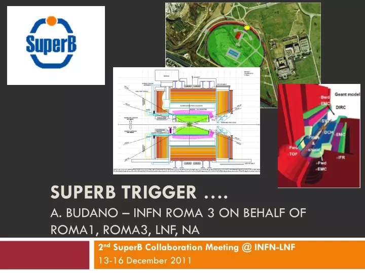
SuperB Trigger ….A. Budano – INFN Roma 3 on behalf of Roma1, Roma3, LNF, Na 2ndSuperB Collaboration Meeting @ INFN-LNF 13-16 December 2011
Let’s remember the specs in SuperB • :re-implement BaBar L1 trigger with some improvements • Shorter latency (~6ms instead of 12ms) • Higher sampling frequencies (DCH and EMC) • 2-d map for calorimeter • Possible additions • SVT trigger • Bhabha Veto • Do we need an absolute time stamp at the trigger level? • Challenge • To keep the event loss due to dead time below 1% => a maximum of ~60ns “per-event dead time” is allowed in trigger and FCTS. • This requirements pushes for trigger time resolution • of about 10-15 ns it could be hard to reach. • This requested has been partly eased. Latest studies from D. Breton slides 150kHz Exponential Inter-arrival time pdf. S. LUTZ 2010
BaBar: Trigger Layout J. C. Andress et Al., “BaBar Calorimeter Level 1 Trigger Design” , BaBar Note (1998)
Calorimeter trigger (requirements) • Itworksindependently from the DC trigger. • It’sbased on the topology of the energydeposits. • Wewouldlike to have an architecturesimilar to DC in order to use the same HW. • As in the case of DC oneitshouldhave a shorterlatency and a good trigger time resolution (about 10 -15 ns).
What we learnt from CsI • Different measures in different conditions on single crystalsruled out the possibility to use PiN diodes or even APD. The measured resolution spanned from 30 to 50 ns. See P. Branchini London or this report from V. Bocci.
What about the detectors? • Wehavelearntthat SVT DAQ windowis 300 ns. Stilldemandingbutnot so bad. The limitisthe intrinsicjitter of the sub-detector. • For the DC the DAQ windowisabout 1 ms. • The minimum DAQ windowbelongs to IFR and itis 150 ns (desired) 100 ns (is the real minimum).
SuperB EMC • EMC Barrel : • 5760 CsI(Tl) Crystals EMC Forward = 4400 LysoCrystals (176 modules) For the moment there are different options for the forward EMC. Lyso is to be considered a case study.
EMC Topology • There are several mechanical constraints from barrel EMC this implays 9 degree modularity for the EMC (3 crystals in f). • The f at the calorimeter covered by each card reading the DC had better match with the calorimeter f granularity. 48 channels reading a supercell would imply a coverage of 36 degrees. • Each DC FE TSF treats the signal from 48 or 64 channels (this matches the DC FE board). 480 towers from the Barrel EMC
EMC fast trigger and energy paths Energy accurate measurement path Double Range shaper Range (0,1) CSP X Ncryst Trigger Fast Path Analog S Pulse Encoder n LVDS Parallel readout SiPm? this part should be rad-hard (to be investigated).
Let’s follow the trigger path Concentrator: Link reduction stage To trigger crates 480 LVDS link in the barrel EMC. The information Stored is the «trigger time assertion» and energy in the width of the signal. An LVDS like signal driven by an actel could be good candidate to do That, if a better solution cannot be found. Here we could be far enough or even shielded from radiation. Moreover this link reduction is not strictly necessary.
EMC possible trigger crate layout EM3 EM2 EM1 EM10 EML9 M A S T E R L M A S T E R 0 M A S T E R R C P U EM1 from 1 to 10 have The f image of the barrel EMC. The Master(s) have the Full EMC informations. Possibly far from detector. We should not have problems from radiation. We are studying the possibility to use mTCA as a backplane.
EMC trigger algorithm (BaBar) • Towerenergywasadded in fbins over the entirebarrel. • A Y sum over the tworearmosttower in the barrelwasdefined. • A X sum for the forward end-cap. Each of these sum wasthencompared with an energy thresholdcorresponding to: • Eclu > 0.120 GeV (Minimum ionizing M cluster) • Eclu> 0.160 GeV (E Cluster) • Eclu > 0.5 GeV (G cluster) • Eclu > 0.120 GeV (X cluster forward end-cap) • Eclu> 2.0 GeV (Y cluster backwardend-cap)
EMC Open problems: • Shorterlatency • trigger time jitter (in BaBar 1 ms) area aiming at some 10 ns. As long aslatencyisconcerned: It’sconditioned by the trigger strategyexploited, Moreover in BaBaritwas7.2 ms.
Barrel CsI (Tl doped) original BaBar P. D. Dauncey et Al., “Design and performance of the level 1 calorimeter trigger for the BABAR detector” (2001) 3 thresholds applied to the signal of the tower. The plot shows the difference between the EMC trigger time and the DC trigger time. A FIR Filter with 8 parameters was applied to the signal. Its zero crossing occurred at roughly a fixed time distance from the start of the signal, it was used to gate the threshold information. Due to this mechanism the time resolution was hundreds of ns. m+m- events used to select good resolution in DC.
EMC BaBar strategy for trigger assertion comments • Trigger latencywas 7.2 ms, 6 ms seemsreachable with thisapproach. • Itturned out the the 1 ms maximum trigger time jitterwasNOTdominated by the detector. Nevertheless a contributionspanning from 30 ns to 50 ns ishasbeenmeasured.
SiPM Front End Electronics for tbeam The master set thresholds and the SiPm voltages. Each board read 8 channels splits the signal to be read by a QDC and a TDC. We’ll use the setup to measure the time resolution of the CsI (tl doped) crystal.
BaBar/SuperB DC sketch In SuperB all stereo layers in between U2 and V9. Moreover A1 has 8 radial wires rather than 4. From the trigger point of view We could divide A1 in 2 superlayers and have 11 equivalent SLs structure.
DC SuperB present-1 design Number of wire could increase due to internal radius uncertainties. The 48 vs 64 depends on the form factor of the FE board used at the moment a conservative assumption has been made (i.e. 6U VME form factor)
DC SuperB present design Super B detector 1504 wires from DC FE crate SL1 472 wires from DC FE crate SL2 536 wires from DC FE crate SL3 600 wires from DC 8056 wires from DC FE crate SL4 664 wires from DC FE crate SL5 728 wires from DC FE crate SL6 792 wires from DC FE crate SL7 856 wires from DC FE crate SL8 920 wires from DC FE crate SL9 984 wires from DC FE crate SL10 246 wires on SL10 isnotwhatwewouldlike to match the EMC sector in F. 240 would be betterbecause in this case wewouldhave 40 cells a perfect match with 9 degree EMC sector.
DC SuperB present design Test Discriminator needed @tbeam FE crate Super layer 10 • • • DC FRONT END Discriminator DC FRONT END Discriminator DC FRONT END Discriminator CPU copper/optical link copper/optical link copper/optical link ethernet link Input signals from DC front end 64 channels 64 channels 64 channels • • • • • discriminated signals In SuperB the discriminator board becomes a mez card and can be upgraded in order to compute TSFs and deliver them through a copper or optical link if there are radiation problems. Otherwise the «standard» solution would be welcome.
RF emulator needed @tbeam • We have also built a ring oscillator to emulate RF when a machine trigger occurs. • And a transition board to feed Virtex6 demo board with LVDS signals.
TrackSegmentFinder (TSF) • The problem of this trigger moduleis to find the best tracksegment(s) in the monitoredsupercell. A radtollerantactelcould do the job. • In BaBar the signaldelivered from each single wirewas sent to a discriminator sampled ad 3.7 MHz. Hitswerethenbroadcasted to the TSFs (24 samestrategywouldimply 64 links in SuperB) throughopticallinks. • In SuperBwemighthave an highersampling to improve the trigger time resolution. Neverthelesssincewehave 132 sources (worst case) the link wecould use needs in principle a lowbandwidth. Let’s take for example a 14.8 MHz sampling. Each link delivers the information of 64 wires to the DC trigger crate. So the bandwidth is:14.8MHz*64 = 947 Mbit/s. I think a more robustthoughlessperformant link could be enoughif a better «rad hard» solutioncan’t be found. This link in principlecouldavoidusinglasers and photon detector. • wecouldalso integrate the TSF on the FE DC crates. Thisallowsus to shrinklatency. A highersamplingcould be allowed and in principleeven a clockless discriminator could be used. The trigger time jitter, PT and zed coordinate measurementshould in principle benefit from that. Wewillstudy the 2 optionsexploiting the LNF prototype.
TSF (Track Segment Finder) 4 pattern for a fixed pivot tube. The other 4 pattern can be found via a parity transformation. So in this example there are 8 patterns per pivot tube and 4 pivot tubes. In total 32 combinations. 5 bits are enough to code the info. 14.8 MHz sampling means 74 Mbit/s link. P P P P
TSF (Track Segment Finder) BaBar SuperB in this example sampling is twice the BaBar one
TSF (trigger time jitter in BaBar) In Babar 3 strategies were examined. 1) First tick with 1.5 tracks present. 2) Last tick with 1.5 tracks present. 3) Last tick with 4 out of four segments. Different latency and trigger jitter time were determined. Trigger criterion:1.5 track With this strategy we are dominated by the sampling frequency
What could be done (if necessary) From BaBar note 319 23/8/1996 Weight each track segment latency with its own error. Apply a weighted average on all the gathered TSFs Sigma is about 14.8 ns when sampling at 3.7 MHz and 10 when sampling at 7.4 MHz A drawback: the precision depends on TSF number: physics of the final state We could use an Hw processor on the trigger crate to implement this algorithm.
DC trigger crates possible layout FE crate Super layer 10 FE crate Super layer 1 • • • • • • DC FRONT END Discriminator DC FRONT END Discriminator DC FRONT END Discriminator DC FRONT END Discriminator DC FRONT END Discriminator DC FRONT END Discriminator CPU CPU • • • • • • copper/optical link copper/optical link copper/optical link copper/optical link copper/optical link copper/optical link • • • • • • 64 channels 64 channels 64 channels 64 channels 64 channels 64 channels ethernet link ethernet link • • • • • • • • • • • • Link sl4 Link sl9 Link sl7 Link sl10 Link sl1 Link sl2 Link sl5 Link sl8 Link sl6 Link sl3 CPU TSF SL10 TSF SL9 TSF SL8 TSF SL7 TSF SL6 TSF SL5 TSF SL4 TSF SL3 TSF SL2 TSF SL1 Master Trigger crate ethernet link
Binary Track Linker Pt and z measurement SL3 SL2 SL1 SL10 SL9 M A S T E R L M A S T E R 0 M A S T E R R C P U SL1 has 8 radial wires in the Present design. Should we not manage to cast them in a single Board we could cast it in 2 boards. Up to 24 optical links (TSF) per board. This topology can implement Kinoshita directly on the crate to find a track. Moreover the Masters have the full DC info and therefore can implement kinoshita with any granularity and compute PT and z measurements.
A possible sketch of trigger system in SuperB DC and EMC trigger crates have a common inteface (LVDS or optical) with pertaining sub-detectors. EMC(i) and DC(i) boards share a common hw platform and only differ in firmware.