Download
1 / 75
830 likes | 1.16k Views
Wing Trade Study. Wing Process Flowchart. CFD (In)Validation. Cruise Wing Optimization. Cruise wing optimization Guidelines. Maintain the same or lower drag Increase lift by 300 pounds Maintain the same or lower surface area, and maintain the same or lower wingspan

E N D
Cruise wing optimization Guidelines • Maintain the same or lower drag • Increase lift by 300 pounds • Maintain the same or lower surface area, and maintain the same or lower wingspan So, improve lift to drag ratio and wing loading of the baseline wing. Note, only considering cruise conditions at the moment.
Airfoil Selection Two different airfoil shapes were investigated in xfoil in order to determine the effect of camber on L/D and maximum Cl.
Airfoil Selection Curves made in x-foil. Both plots are of airfoil 1 with varying cambers at Re=6 million
Airfoil selection Curves made in x-foil. Both plots are of airfoil 2 with varying cambers at Re=6 million
Deep Chamber-High Lift-Low Speed-Thick Wing Section-Good For Transport, Freighters and Bomber Planes.
Root: ARA-D 6% Tip: N-14
Airfoil: Root: ARA-D 6% Tip: N-14 Actual
Root: ARA-D 10% Tip: N-14
Airfoil: Root: ARA-D 10% T: N-14 Actual
Root: GOE 619AT18.5 Tip: S8035 for RC aerobatic 14% thick
Airfoil: Root: GOE 619 Tip: S8035 for RC aerobatic 14% thick ACTUAL
Root: FX 66-182 Tip: FX 63-137 13.7%
Airfoil: Root: FX 66-182 Tip: FX 63-137 13.7% Actual
Airfoil 2: Root: FX 66-182 Tip: FX 63-137 13.7% Actual
Leading edge slats accelerate the air in the funnel shaped slot (venturi effect) and blow the fast air tangentially on the upper wing surface through the much smaller slot. This "pulls" the air around the leading edge, thus preventing the stall up to a much higher angle of attack and lift coefficient (approximately 30 degrees). It does this by picking up a lot of air from below, where the slot is large, the disadvantage of the leading edge slat is that the air accelerated in the slot requires energy which means higher drag. As the high lift is needed only when flying slowly (take-off, initial climb, and final approach and landing) the temptation for the designer is to use a retractable device which closes at higher speeds to reduce drag. Changing from a plain airfoil to an airfoil with flaps we have created an increase of curvature of the airfoil which gives part of the extra lift, but we have also created a depression, a low pressure near the trailing edge, which sucks the air over the upper part of the airfoil and helps it to overcome the centrifugal forces present when the air flow has to come around the nose of the wing. It is like a pull acting from the trailing edge and pulling the air around the leading edge, thus preventing separation
Actual Plain Flap at AOA of 13
Plain Flaps And Stats
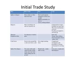
Fowler flap study 1 non-slotted fowler design Need track system Most increase in lift 2 slotted fowler flap designs Can use offset hinge Less increase in lift
Non-slotted fowler flap • Provides the highest increase in surface area • Requires largest movement of flap
Slotted fowler flap Doesn’t provide as much increase in wing area Doesn’t require as much movement
Non-slotted flap design from “AERODYNAMIC CHARACTERISTICS OF A WING WITH FOWLER FLAPS INCLUDING FLAP LOADS, DOWNWASH, AND CALCULATED EFFECT ON TAKEOFF”, Platt, Robert C, Langley Research Center, 1936, document ID: 19930091607
Non-slotted flap design • Optimum position of leading edge of flap is X=c, Y=-.025c • Optimum flap deflection angle is 40 degrees for Reynolds number of 300,000 Note: optimum position is generally true for most airfoil shapes, but optimum angle isn’t as general, as it also depends on the flap shape too.
Non-slotted flap design 30% of the chord at all stations 104 inches long, which is 48% span of wing (including the portion inside fuselage) 30 degrees deflection, hedging on safety against uncertainty in flow separation Results using sea level conditions at 60 knots: AOA 10, Cl = .55, produces 844.2 pounds of lift AOA 13, Cl = .52, produces 899.8 pounds of lift, has severe flow seraration
Slotted flap design guidelines • Optimum position of flap leading edge depends primarily on the shape of the slot, and is best determined by experiment • In general, moves inward when lip is increased but is generally about .01c forward of lip • Usually a slot opening on the order of .01c or slightly more is best. • Best Cl’s are achieved using flaps with a wing shape. Avoid flaps with blunt leading edge. from “Theory of wing sections”, Ira H. Abbott and Albert E. von Doenhoff, p. 212-213. Dover Publications, NY, 1959.
Slotted flap design Two different shapes of slots with different flap shapes. The one on the right has a small lip with max cl=2.57, the one on the left is a smooth slot with max cl=2.35.
Slotted flap design On the left is a slot with a larger lip and with a maximum Cl=2.65. On the right is a plot of the effect slot entry radius has on maximum Cl. from “Wind-tunnel investigation of an NACA 23012 airfoil with various arrangements of slotted flaps”, Wenzinger, Carl J; Harris , Thomas A, Langley Research Center, 1939, ID: 19930091739
Slotted flap design 1 30% of the chord at all stations 104 inches long, which is 48% span of wing (including the portion inside fuselage) 30 degrees deflection Results using sea level conditions at 60 knots: AOA 10, Cl = .6, produces 840.5 pounds of lift AOA 13, Cl = .7, produces 980.5 pounds of lift
Slotted flap 1 with slot in flap 30% of the chord at all stations 104 inches long, which is 48% span of wing (including the portion inside fuselage) 30 degrees deflection Results using sea level conditions at 60 knots: AOA 10, Cl = .6, produces 841.5 pounds of lift AOA 13, Cl = .8, produces 1125.4 pounds of lift
Slotted flap design 2 30% of the chord at all stations 104 inches long, which is 48% span of wing (including the portion inside fuselage) 30 degrees deflection Results using sea level conditions at 60 knots: AOA 10, Cl = .63, produces 883 pounds of lift AOA 13, Cl = .75, produces 1050 pounds of lift
Slotted flap 2 with slot in flap 30% of the chord at all stations 104 inches long, which is 48% span of wing (including the portion inside fuselage) 30 degrees deflection Results using sea level conditions at 60 knots: AOA 10, Cl = .65, produces 916 pounds of lift AOA 13, Cl = .654, produces 921 pounds of lift
Comparison Non-slotted flap was calculated to have the least lift. Slotted flap 1 produced more lift with a slot in the flap at AOA 13 than slotted flap 2. Slotted flap 2 produced more overall lift without a slot in the flap than slotted flap 1. Conclusion: Design 2 is better, but the slot on the flap isn’t optimized.
COSTS / BENEFITS • COSTS • Increased drag when compared to non-deployed flapperons. Possibly caused by flow separation due to gap between wing and flapperon when deployed. • Could be difficult to work mechanically with the pulley system in place now. • Hard to control during landing due to adverse yaw effects.
BENEFITS • Increase camber during landing. • Increase lift due to increased camber. • Optimal position is with flapperons deployed 40°