Download
1 / 23
230 likes | 246 Views
Chapter 9 Relational Database Design by ER- and EER-to-Relational Mapping. Chapter 9 Outline. Relational Database Design Using ER-to-Relational Mapping Mapping EER Model Constructs to Relations. Relational Database Design by ER- and EER-to-Relational Mapping.

E N D
Chapter 9 Relational Database Design by ER- and EER-to-Relational Mapping
Chapter 9 Outline • Relational Database Design Using ER-to-Relational Mapping • Mapping EER Model Constructs to Relations
Relational DatabaseDesign by ER- and EER-to-Relational Mapping • Design a relational database schema • Based on a conceptual schema design • Seven-step algorithm to convert the basic ER model constructs into relations • Additional steps for EER model
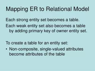
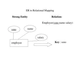
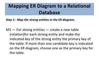
ER-to-Relational Mapping Algorithm • Step 1: Mapping of Regular Entity Types • For each regular entity type, create a relation R that includes all the simple attributes of E • Choose one of the key attributes of E as the primary key for R • If the chosen key of E is composite, the set of simple attributes that form it will together form the primary key of R • Example: We create the relations EMPLOYEE, DEPARTMENT, and PROJECT in the relational schema corresponding to the regular entities in the ER diagram. • SSN, DNUMBER, and PNUMBER are the primary keys for the relations EMPLOYEE, DEPARTMENT, and PROJECT • Called entity relations • Each tuple represents an entity instance
ER-to-Relational Mapping Algorithm (cont’d.) • Step 2: Mapping of Weak Entity Types • For each weak entity type W in the ER schema with owner entity type E, create a relation R & include all simple attributes (or simple components of composite attributes) of W as attributes of R. • Also, include as foreign key attributes of R the primary key attribute(s) of the relation(s) that correspond to the owner entity type(s) • The primary key of R is the combination of the primary key(s) of the owner(s) and the partial key of the weak entity type W, if any • Example: Create the relation DEPENDENT in this step to correspond to the weak entity type DEPENDENT. • Include the primary key SSN of the EMPLOYEE relation as a foreign key attribute of DEPENDENT (renamed to ESSN). • The primary key of the DEPENDENT relation is the combination {ESSN, DEPENDENT_NAME} because DEPENDENT_NAME is the partial key of DEPENDENT.
ER-to-Relational Mapping Algorithm (cont’d.) • Step 3: Mapping of Binary 1:1 Relationship Types • For each binary 1:1 relationship type R in the ER schema, identify the relations S and T that correspond to the entity types participating in R. • Possible approaches: • Foreign key approach - Choose one of the relations-say S-and include a foreign key in S the primary key of T. It is better to choose an entity type with total participation in R in the role of S. • Example: 1:1 relation MANAGES is mapped by choosing the participating entity type DEPARTMENT to serve in the role of S, because its participation in the MANAGES relationship type is total • Merged relationship- An alternate mapping of a 1:1 relationship type is possible by merging the two entity types and the relationship into a single relation. This may be appropriate when both participations are total. • Crossreference or relationship relation approach- The third alternative is to set up a third relation R for the purpose of cross-referencing the primary keys of the two relations S and T representing the entity types.
ER-to-Relational Mapping Algorithm (cont’d.) • Step 4: Mapping of Binary 1:N Relationship Types • For each regular binary 1:N relationship type R, identify the relation S that represent the participating entity type at the N-side of the relationship type. Identify relation that represents participating entity type at N-side of relationship type • Include as foreign key in S the primary key of the relation T that represents the other entity type participating in R. • Include any simple attributes of the 1:N relation type as attributes of S • Example: 1:N relationship types WORKS_FOR, CONTROLS, and SUPERVISION in the figure. • For WORKS_FOR we include the primary key DNUMBER of the DEPARTMENT relation as foreign key in the EMPLOYEE relation and call it DNO
ER-to-Relational Mapping Algorithm (cont’d.) • Alternative approach • Use the relationship relation (cross-reference) option as in the third option for binary 1:1 relationships
ER-to-Relational Mapping Algorithm (cont’d.) • Step 5: Mapping of Binary M:N Relationship Types • For each regular binary M:N relationship type R, create a new relation S to represent R. • Include as foreign key attributes in S the primary keys of the relations that represent the participating entity types; their combination will form the primary key of S. • Also include any simple attributes of the M:N relationship type (or simple components of composite attributes) as attributes of S. • Example: The M:N relationship type WORKS_ON from the ER diagram is mapped by creating a relation WORKS_ON in the relational database schema. • The primary keys of the PROJECT and EMPLOYEE relations are included as foreign keys in WORKS_ON and renamed PNO and ESSN, respectively. • Attribute HOURS in WORKS_ON represents the HOURS attributeof the relation type. The primary key of the WORKS_ON relation isthe combination of the foreign key attributes {ESSN, PNO}.
ER-to-Relational Mapping Algorithm (cont’d.) • Step 6: Mapping of Multivalued Attributes • For each multivalued attribute A, create a new relation R. • This relation R will include an attribute corresponding to A, plus the primary key attribute K-as a foreign key in R-of the relation that represents the entity type of relationship type that has A as an attribute. • The primary key of R is the combination of A and K. If the multivalued attribute is composite, we include its simple components. • Example: The relation DEPT_LOCATIONS is created. The attribute DLOCATION represents the multivalued attribute LOCATIONS of DEPARTMENT, while DNUMBER-as foreign key represents The primary Key of The DEPARTMENT relation. • The primary key of R is the combination of {DNUMBER,DLOCATION}.
ER-to-Relational Mapping Algorithm (cont’d.) • Step 7: Mapping of N-ary Relationship Types • For each n-ary relationship type R, where n>2, create a new relationship S to represent R. • Include as foreign key attributes in S the primary keys of the relations that represent the participating entity types. • Also include any simple attributes of the n-ary relationship type (or simple components of composite attributes) as attributes of S. • Example: The relationship type SUPPY in the ER on the next slide. • This can be mapped to the relation SUPPLY shown in the relational schema, whose primary key is the combination of the three foreign keys {SNAME, PARTNO, PROJNAME}
Discussion and Summary of Mapping for ER Model Constructs (cont’d.) • In a relational schema relationship, types are not represented explicitly • Represented by having two attributes A and B:one a primary key and the other a foreign key
Mapping EER Model Constructs to Relations • Extending ER-to-relational mapping algorithm
Mapping of Specialization or Generalization • Step 8: Options for Mapping Specialization or Generalization (see pages 294-295) • Option 8A: Multiple relations—superclass and subclasses • For any specialization (total or partial, disjoint or overlapping) • Option 8B: Multiple relations—subclass relations only • Subclasses are total • Specialization has disjointedness constraint
Mapping of Specialization or Generalization (cont’d.) • Option 8C: Single relation with one type attribute • Type or discriminating attribute indicates subclass of tuple • Subclasses are disjoint • Potential for generating many NULL values if many specific attributes exist in the subclasses • Option 8D: Single relation with multiple type attributes • Subclasses are overlapping • Will also work for a disjoint specialization
Mapping of Shared Subclasses (Multiple Inheritance) • Apply any of the options discussed in step 8 to a shared subclass
Mapping of Categories (Union Types) • Step 9: Mapping of Union Types (Categories) • Defining superclasses have different keys • Specify a new key attribute • Surrogate key
Summary • Map conceptual schema design in the ER model to a relational database schema • Algorithm for ER-to-relational mapping • Illustrated by examples from the COMPANY database • Include additional steps in the algorithm for mapping constructs from EER model into relational model