Download
1 / 54
780 likes | 1.52k Views
Mapping ER-EER to Relational Model. Relational Model Review - Concepts. Relational Model is made up of tables A row of table = a relational instance/ tuple A column of table = an attribute A table = a schema/relation Cardinality = number of rows

E N D
Relational Model Review - Concepts Relational Model is made up of tables • A row of table = a relational instance/tuple • A column of table = an attribute • A table = a schema/relation • Cardinality = number of rows • Degree = number of columns
Review - Example Attribute Cardinality = 2 tuple/relational instance 4 Degree A Schema / Relation
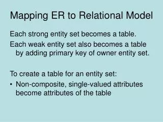
ER to Relational Mapping So… how do we convert an ER diagram into a table?? Simple!! Basic Ideas: • Build a table for each entity set • Build a table for each relationship set if necessary (more on this later) • Make a column in the table for each attribute in the entity set • Composite and Multivalue Attributes • Primary Key
ER\EER to Relational Mapping • ER-to-Relational Mapping Algorithm • Step 1: Mapping of Regular Entity Types • Step 2: Mapping of Weak Entity Types • Step 3: Mapping of Binary 1:1 Relationship Types • Step 4: Mapping of Binary 1:N Relationship Types • Step 5: Mapping of Binary M:N Relationship Types • Step 6: Mapping of Multivaluedattributes • Step 7: Mapping of N-ary Relationship Types • Mapping EER Model Constructs to Relations • Step 8: Mapping of Specialization or Generalization • Step 9: Mapping of Union Types (Categories)
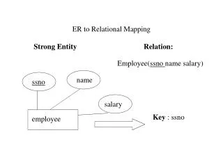
Mapping – Strong Entity Set SID Name SSN Name Advisor Student Professor Dept Major GPA
Mapping of Weak Entity • Weak Entity Set Cannot exists alone • To build a table/schema for weak entity set • Construct a table with one column for each attribute in the weak entity • Add a column for the primary key of the Owner of the Weak Entity • Primary Key of the weak entity = Discriminator + foreign key
Mapping - Weak Entity Set Age SID Name Name Student owns Children Major GPA • Mapping Rule • Construct a table with one column for each attribute in the weak entity • Add primary key of the Owner Entity in the table * Primary key of Children is Parent_SID + Name
Mapping of Relationships --This is a little complicated— • Unary/Binary Relationship set • Depends on the cardinality and participation constraints • N-ary(multiple) Relationship set • Identifying Relationship
Mapping Relationship SetUnary/Binary Relationship • 1-1 relationship without total participation • Relationship relation: Build a table and add columns for each participating entity’s primary key. Also add the attributes of the relationship. (cross-reference) • 1-1 relationship with one total participation • Foreign key approach: Add primary key of the entity without total participation in the table of the entity with total participation. • Merged relation (alternate mapping): merge the two entities and the relationship into a single relation (used when both participations are total).
Example: Relationship Relation Date SID Name S\N # 1 1 Student Assigned Laptop Major Major GPA Brand * Primary key can be either SID or S\N#
Example: Foreign Key Approach Date SID Name S\N # 1 1 Student Assigned Laptop Major Major GPA Brand
FIGURE 7.1The ER conceptual schema diagram for the COMPANY database.
Representing Relationship SetUnary/Binary Relationship • 1-N relationship without total participation • Same as 1-1 relationship • Relationship relation: Build a table and add columns for each participating entity’s primary key. Also add the attributes of the relationship. (cross-reference) • 1-N with total participation on Nside • Foreign key approach : Add a column in the table of the entity on the Nside, put in there the primary key of the entity on the 1 side.
Example – 1:N Relationship Set Semester SID Name SSN N 1 Advisor Student Professor Major GPA Dept Name * Primary key of this table is SID
FIGURE 7.1The ER conceptual schema diagram for the COMPANY database.
Representing Relationship SetUnary/Binary Relationship • N:M relationship • Relationship relation: Build a table and add columns for each participating entity’s primary key. Also add the attributes of the relationship. (cross-reference) • Primary key of this new table is the union of the foreign keys of both entity sets. • Note No Foreign Key approach is possible…
FIGURE 7.1The ER conceptual schema diagram for the COMPANY database.
Representing Relationship SetN-ary Relationship • Intuitively Simple • Build a new table, add primary keys of all participating entity sets. • Add attributes of the relationship set • The primary key of this new table is the union of all primary keys of entities that are on N side • That is it, we are done.
Example – N-ary Relationship Set P-Key1 D-Attribute A-Key E-Set 1 N N 1 P-Key2 relationship Another Set E-Set 2 N P-Key3 E-Set 3 * Primary key of this table is P-Key1 + P-Key2 + P-Key3
FIGURE 4.11Ternary relationship types. (a) The SUPPLY relationship.
Representing Relationship SetIdentifying Relationship • Don't create a table for the identifying relationship • As we have built a table for the corresponding weak entity • Reason: • A special case of 1:N with total participation • Reduce Redundancy
Representing Composite Attribute • One column for each component attribute • NO column for the composite attribute itself SSN Name Professor Address Street City
Representing Multivalue Attribute • Build a new relation schema with two columns • Add the primary keys of the entity/relationship that has the multivalue attribute • Add the multivalueattribute. • Each cell of this column holds only one value. So each value is represented as an unique tuple • Primary key for this schema is the union of all attributes
Example – Multivalue attribute The primary key for this table is Student_SID + Degree, the union of all attributes SID Name Degree Student Major GPA
Correspondence between ER Model & Relational Model ER Model Relational Model • Entity type • 1:1 or 1:N relationship type • M:N relationship type • n-ary relationship type • Simple attribute • Composite attribute • Multivalued attribute • Value set • Key attribute • Entity relation • Foreign key (or relationship relation) • Relationship relation and two foreign keys • Relationship relation and n foreign keys • Attribute • Set of simple component attributes • Relation and foreign key • Domain • Primary (or secondary) key
ER to Relational: Example Football Club “A football club has a name and a ground and is made up of players. A player can play for only one club. A manager, represented by his name manages a club. A footballer has a registration number, name and age. A club manager also buys players. Eachclub plays against other clubs in the league and matches have a date, venue and score.” Dark lines represent total participation
Mapping EER Model Constructs to Relations • For Mapping Specialization or Generalization we have four options: • Multiple relations-Superclass and subclasses • Multiple relations-Subclass relations only • Single relation with one type attribute • Single relation with multiple type attributes
Mapping EER Model Constructs to Relations • Multiple relations- Superclassand Subclasses • Create a relation for the Superclass • Create a relation for each subclass and also include the primary key of the Superclass • This option works for any specialization (total or partial, disjoint or over-lapping).
Mapping EER Model Constructs to Relations • Multiple Relations-Subclass relations only • Create a relation for each subclass and include the attributes of the superclass in each subclass relation • This option only works for a specialization whose subclasses are total • Every entity in the superclassmust belong to at least one of the subclasses. • It is preferred that subclasses are disjoint (to avoid redundancy) • Need Outer join (or full outer join) to get all entities
Generalizing CAR and TRUCK into the superclass VEHICLE. Tonnage
Mapping EER Model Constructs to Relations • Single relation with one type attribute • Create a single relation for superclass and all of the subclasses • The new relation includes the attributes of superclass and all the attributes of each subclass • The relation also includes an attribute type (or discriminating attribute) that indicates the subclass to which each tuplebelongs • Not recommended if subclasses have many attributes
Mapping EER Model Constructs to Relations • Single relation with multiple type attributes • Create a single relation for superclass and all of the subclasses • The new relation includes the attributes of superclass and all the attributes of each subclass • The relation also includes m type attributes, that is {t1, t2,…,tm}, where m is the no of subclasses. • Each ti, 1 < i< m, is a Boolean type attribute indicating whether a tuple belongs to the ith subclass.
FIGURE 4.5EER diagram notation for an overlapping specialization. O
Mapping of Shared Subclasses (Multiple Inheritance) • A shared subclass, is a subclass of several classes, indicating multiple inheritance. • These classes must all have the same key attribute. WHY ? • Otherwise, the shared subclass would be modeled as a category. • We can apply any of the options discussed before for Specialization\Generalization to a shared subclass, subject to the restriction.
FIGURE 4.7A specialization lattice with multiple inheritance for a UNIVERSITY database.
FIGURE 7.5Mapping the EER specialization lattice in Figure 4.6 using multiple options.
Mapping of Union Types (Categories) • For mapping a category whose superclasshave different keys, we specify a new key attribute, called a surrogate key.
FIGURE 4.8Two categories (union types): OWNER and REGISTERED_VEHICLE. OwnerId