Download
1 / 1
10 likes | 157 Views
(3) Optimum beam-forming = Beam-steering + null-steering Continuous pattern optimisation, i.e. optimisation of the weighting coefficients W i ’s so as to: - Maximise the signal-to-noise ratio (SNR) - Maximise the signal-to-clutter ratio (SCR).

E N D
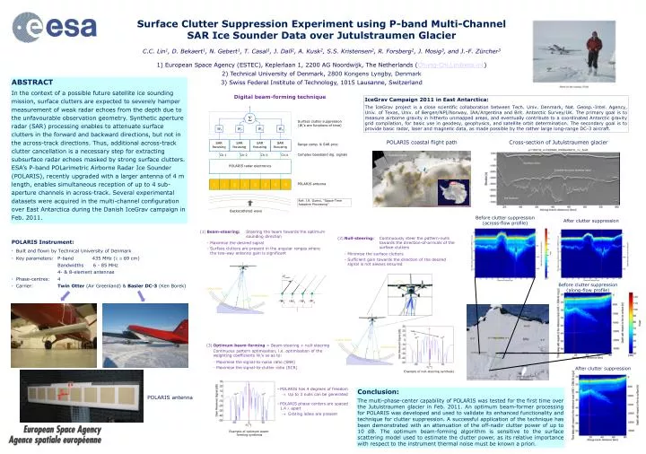
(3) Optimum beam-forming = Beam-steering + null-steering • Continuous pattern optimisation, i.e. optimisation of the weighting coefficients Wi’s so as to: • - Maximise the signal-to-noise ratio (SNR) • - Maximise the signal-to-clutter ratio (SCR) (1) Beam-steering: Steering the beam towards the optimum sounding direction - Maximise the desired signal - Surface clutters are present in theangular ranges where the two-wayantenna gain is significant Surface Clutter Suppression Experiment using P-band Multi-Channel SAR Ice Sounder Data over Jutulstraumen Glacier C.C. Lin1, D. Bekaert1, N. Gebert1, T. Casal1, J. Dall2, A. Kusk2, S.S. Kristensen2, R. Forsberg2, J. Mosig3, and J.-F. Zürcher3 1) European Space Agency (ESTEC), Keplerlaan 1, 2200 AG Noordwijk, The Netherlands (Chung-Chi.Lin@esa.int) 2) Technical University of Denmark, 2800 KongensLyngby, Denmark 3) Swiss Federal Institute of Technology, 1015 Lausanne, Switzerland Surface clutter suppression (Wi’s are functions of time) Coastal flights W1 W2 W3 W4 SAR focusing SAR focusing SAR focusing SAR focusing Range comp. & SAR proc. • POLARIS has 4 degrees of freedom • Up to 3 nulls can be generated • POLARIS phase-centers are spaced 1.4 apart • Grating lobes are present Surface echo Complex baseband dig. signals Ch-1 Ch-2 Ch-3 Ch-4 Double bounce surface echo Surface clutter Surface clutter POLARIS radar electronics Surface clutter Surface clutter POLARIS antenna Ice bottom Ref: J.R. Guerci, “Space-Time Adaptive Processing” 1 1 2 2 3 3 4 4 Example of optimum beam-forming ABSTRACT In the contextof a possible future satellite ice sounding mission, surface clutters are expected to severely hamper measurement of weak radar echoes from the depth due to the unfavourable observation geometry. Synthetic aperture radar (SAR) processing enables to attenuate surface clutters in the forward and backward directions, but not in the across-track directions. Thus, additional across-track clutter cancellation is a necessary step for extracting subsurface radar echoes masked by strong surface clutters. ESA’s P-band POLarimetric Airborne Radar Ice Sounder (POLARIS), recently upgraded with a larger antenna of 4 m length, enables simultaneous reception of up to 4 sub-aperture channels in across-track. Several experimental datasets were acquired in the multi-channel configuration over East Antarctica during the Danish IceGrav campaign in Feb. 2011. Backscattered wave Example of null-steering synthesis Digital beam-forming technique IceGrav Campaign 2011 in East Antarctica: The IceGrav project is a close scientific collaboration between Tech. Univ. Denmark, Nat. Geosp.-Intel. Agency, Univ. of Texas, Univ. of Bergen/NPI/Norway, IAA/Argentina and Brit. Antarctic Survey/UK. The primary goal is to measure airborne gravity in hitherto unmapped areas, and eventually contribute to a coordinated Antarctic gravity grid compilation, for basic use in geodesy, geophysics, and satellite orbit determination. The secondary goal is to provide basic radar, laser and magnetic data, as made possible by the rather large long-range DC-3 aircraft. POLARIS coastal flight path Cross-section of Jutulstraumen glacier Before clutter suppression (across-flow profile) After clutter suppression (2) Null-steering: Continuously steer the pattern-nulls towards the direction-of-arrivals of the surface clutters - Minimise the surface clutters - Sufficient gain towards the direction of the desired signal is not always ensured • POLARIS Instrument: • Built and flown by Technical University of Denmark • Key parameters: P-band 435 MHz ( 69 cm) • Bandwidths 6 - 85 MHz • 4- & 8-element antennas • Phase-centres: 4 • Carrier: Twin Otter (Air Greenland) & Basler DC-3 (Ken Borek) Before clutter suppression (along-flow profile) After clutter suppression Conclusion: The multi-phase-center capability of POLARIS was tested for the first time over the Jutulstraumen glacier in Feb. 2011. An optimum beam-former processing for POLARIS was developed and used to validate its enhanced functionality and technique for clutter suppression. A successful application of the technique has been demonstrated with an attenuation of the off-nadir clutter power of up to 10 dB. The optimum beam-forming algorithm is sensitive to the surface scattering model used to estimate the clutter power, as its relative importance with respect to the instrument thermal noise must be known a priori. POLARIS antenna Example of optimum beam-formingsynthesis