Download
1 / 10
110 likes | 237 Views
High Speed Digital Signal Lab. Cross Hole Ultrasonic Monitor. Characterization Presentation. Students : Lotem Sharon Yuval Sela. Instructor : Ina Rivkin. Background. Cross Hole Ultrasonic Monitor (CHUM) system made by Piletest Quality control of deep concrete foundation

E N D
High Speed Digital Signal Lab Cross Hole Ultrasonic Monitor Characterization Presentation Students: Lotem Sharon Yuval Sela • Instructor : Ina Rivkin
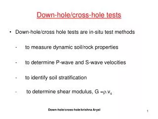
Background • Cross Hole Ultrasonic Monitor (CHUM) system made by Piletest • Quality control of deep concrete foundation • Ultrasonic waves through the concrete • Measuring the energy and the first arrival time
Motivation • The current CHUM uses sample rate of 500kHz, complying American standard. • A necessity came up to comply with the 1MHz French standard. Goal • Developing a board based on FPGA, • that samples data at rates of up to 1MHz, • and connects to the Micro-Controller • Experimenter Board.
Block diagram • Analog Devices AD7671 LQFP48 Analog /Digital Converter • Altera FPGA Cyclone IV EP4CE6 EQFP144 • Texas Instruments Micro-Controller MSP430F5419AIPZ, on MSP-EXP430F5438 Experimenter Board High speed Low speed To user interface Micro-Controller Analog from Rx FPGA (FIFO) ADC 1MHz
Specifications • The FPGA receives a 16-bit data from ADC, in 1MHz. • It stores 2 kilo-words in a FIFO memory, and makes it accessible to the µC at lower speed, by a 8-bit bus. • The system works on a battery, thus it has to be energy efficient.
Our Board POWER JTAG 16-Bit Data 8-Bit Data ADC FPGA Clock Control RESET
Micro Controller Experimenter Board • Development environment for Micro Controller • Texas Instruments MSP430F5419AIPZ Micro Controller • JTAG connector to Program / debug • GPIO interface, connects to our board. MSP-EXP430F5438
FPGA State Machine St. Mach. Start=0 Sample Rate=0 Busy=1 Idle Count=0 Count++ FIFO Full=0 Data Write Count++ Data Ready FIFO Full=1 Count=0 St. Mach. Start=1 Sample Rate=1 Busy=0 Count<2048 FIFO RD=1 Count=2048 Count=2048 FIFO RD=1 FIFO RD=0 H/L Byte =1 FIFO RD=1 FIFO RD=1 FIFO RD=0 H/L Byte =0 FIFO RD=0 FIFO RD=0 FIFO RD=0