Download
1 / 42
420 likes | 545 Views
61. AUDIO SYSTEM OPERATION AND DIAGNOSIS. Figure 61-1 Audio systems use both electromagnetic radio waves and sound waves to reproduce sound inside the vehicle. Figure 61-2 The relationship among wavelength, frequency, and amplitude.

E N D
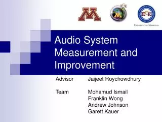
61 AUDIO SYSTEM OPERATION AND DIAGNOSIS
Figure 61-1 Audio systems use both electromagnetic radio waves and sound waves to reproduce sound inside the vehicle.
Figure 61-2 The relationship among wavelength, frequency, and amplitude.
Figure 61-4 The frequency changes in FM broadcasting and the amplitude remains constant.
Figure 61-5 Using upper and lower sidebands allows stereo to be broadcast. The receiver separates the signals to provide left and right channels.
FREQUENTLY ASKED QUESTION: What Does a “Capture” Problem Mean? A capture problem affects only FM reception and means that the receiver is playing more than one station if two stations are broadcasting at the same frequency. Most radios capture the stronger signal and block the weaker signal. However, if the stronger signal is weakened due to being blocked by buildings or mountains, the weaker signal will then be used. When this occurs, it will sound as if the radio is changing stations by itself. This is not a fault with the radio, but simply a rare occurrence with FM radio.
Figure 61-6 The five types of antennas used on General Motors vehicles include the slot antenna, fixed mast antenna, rear window defogger grid antenna, a powered mast antenna, and an integrated antenna.
Figure 61-7 The ground plane is actually one-half of the antenna.
FREQUENTLY ASKED QUESTION: What Is a Ground Plane? Antennas designed to pick up the electromagnetic energy that is broadcast through the air to the transmitting antenna are usually one-half wavelength high, and the other half of the wavelength is the ground plane. This one-half wavelength in the ground plane is literally underground. For ideal reception, the receiving antenna should also be the same as the wavelength of the signal. Because this length is not practical, a design compromise uses the length of the antenna as one-fourth of the wavelength; in addition, the body of the vehicle itself is one-fourth of the wavelength. The body of the vehicle, therefore, becomes the ground plane. - SEE FIGURE 61–7 . Any faulty condition in the ground plane circuit will cause the ground plane to lose effectiveness, such as: • Loose or corroded battery cable terminals • Acid buildup on battery cables • Engine grounds with high resistance • Loss of antenna or audio system grounds • Defective alternator, causing an AC ripple exceeding 50 mV (0.050 V)
Figure 61-8 If all ohmmeter readings are satisfactory, the antenna is good.
TECH TIP: The Hole in the Fender Cover Trick A common repair is to replace the mast of a power antenna. To help prevent the possibility of causing damage to the body or paint of the vehicle, cut a hole in a fender cover and place it over the antenna. - SEE FIGURE 61–9 . If a wrench or tool slips during the removal or installation process, the body of the vehicle will be protected.
Figure 61-9 Cutting a small hole in a fender cover helps to protect the vehicle when replacing or servicing an antenna.
Figure 61-10 A typical power antenna assembly. Note the braided ground wire used to ensure that the antenna has a good ground plane.
Figure 61-11 Between 6 and 7 volts is applied to each speaker terminal, and the audio amplifier then increases the voltage on one terminal and at the same time decreases the voltage on the other terminal causing the speaker cone to move. The moving cone then moves the air, causing sound.
Figure 61-12 A typical automotive speaker with two terminals. The polarity of the speakers can be identified by looking at the wiring diagram in the service manual or by using a 1.5 volt battery to check. When the battery positive is applied to the positive terminal of the speaker, the cone will move outward. When the battery leads are reversed, the speaker cone will move inward.
Figure 61-13 (a) Two 4 ohm speakers connected in series result in total impedance of 8 ohms. (b) Two 4 ohm speakers connected in parallel result in total impedance of 2 ohms.
TECH TIP: Skin Effect When a high-frequency signal (AC voltage) is transmitted through a wire, the majority of it travels on the outside surface of the wire. This characteristic is called skin effect. The higher the frequency is, the closer to the outer surface the signal moves. To increase audio system output, most experts recommend the use of wire that has many strands of very fine wire to increase the surface area or the skin area of the conductor. Therefore, most aftermarket speaker wire is stranded with many smalldiameter copper strands.
WARNING: Hearing loss is possible if exposed to loud sounds. According to noise experts (audiologists), hearing protection should be used whenever the following occurs. 1. You must raise your voice to be heard by others next to you. 2. You cannot hear someone else speaking who is less than 3 ft (1 m) away. 3. You are operating power equipment, such as a lawnmower.
FREQUENTLY ASKED QUESTION: What Is a Bass Blocker? A bass blocker is a capacitor and coil assembly that effectively blocks low frequencies. A bass blocker is normally used to block low frequencies being sent to the smaller front speakers. Using a bass blocker allows the smaller front speakers to more efficiently reproduce the midrange and high-range frequency sounds.
Figure 61-14 Crossovers are used in audio systems to send high-frequency sounds to the small (tweeter) speakers and lowfrequency sounds to larger (woofer) speakers.
Figure 61-15 Two capacitors connected in parallel provide the necessary current flow to power large subwoofer speakers.
Chart 61-1 The rating of the capacitor needed to upgrade an audio system is directly related to the wattage of the system.
Figure 61-16 A powerline capacitor should be connected through the power wire to the amplifier as shown. When the amplifier requires more electrical power (watts) than the battery can supply, the capacitor will discharge into the amplifier and supply the necessary current for the fraction of a second it is needed by the amplifier. At other times when the capacitor is not needed, it draws current from the battery to keep it charged.
Figure 61-17 Voice commands can be used to control many functions, including navigation systems, climate control, telephone, and radio.
FREQUENTLY ASKED QUESTION: What Do the Amplifier Specifications Mean? RMS power RMS means root-mean-square and is the rating that indicates how much power the amplifier is capable of producing continuously. RMS power at 2 ohms This specification in watts indicates how much power the amplifier delivers into a 2 ohm speaker load. This 2 ohm load is achieved by wiring two 4 ohm speakers in parallel or by using 2 ohm speakers. Peak power Peak power is the maximum wattage an amplifier can deliver in a short burst during a musical peak.
Figure 61-18 The voice command icon on the steering wheel of a Cadillac.
Figure 61-19 Bluetooth earpiece that contains a microphone and speaker unit that is paired to a cellular phone. The telephone has to be within 33 ft (10 m) of the earpiece.
FREQUENTLY ASKED QUESTION: Where Did Bluetooth Get Its Name? The early adopters of the standard used the term Bluetooth, and they named it for Harold Bluetooth, the king of Denmark in the late 900s. The king was able to unite Denmark and part of Norway into a single kingdom.
FREQUENTLY ASKED QUESTION: Can Two Bluetooth Telephones Be Used in a Vehicle? Usually. In order to use two telephones, the second phone needs to be given a name. When both telephones enter the vehicle, check which one is recognized. Say “phone status” and the system will tell you to which telephone the system is responding. If it is not the one you want, simply say, “next phone” and it will move to the other one.
Figure 61-20 SDARS uses satellites and repeater stations to broadcast radio.
Figure 61-21 An aftermarket XM radio antenna mounted on the rear deck lid. The deck lid acts as the ground plane for the antenna.
Figure 61-22 A shark-fin-type factory antenna used for both XM and OnStar.
Figure 61-23 A radio choke and/or a capacitor can be installed in the power feed lead to any radio, amplifier, or equalizer.
Figure 61-24 Many automobile manufacturers install a coaxial capacitor, like this one, in the power feed wire to the blower motor to eliminate interference caused by the blower motor.
Figure 61-25 A “sniffer” can be made from an old antenna lead-in cable by removing about 3 in. of the outer shielding from the end. Plug the lead-in cable into the antenna input of the radio and tune the radio to a weak station. Move the end of the antenna wire around the vehicle dash area. The sniffer is used to locate components that may not be properly shielded or grounded and can cause radio interference through the case (housing) of the radio itself.
FREQUENTLY ASKED QUESTION: What Does ESN Mean? ESN means electronic serial number. This is necessary information to know when reviewing satellite radio subscriptions. Each radio has its own unique ESN, often found on a label at the back or bottom of the unit. It is also often shown on scan tools or test equipment designed to help diagnose faults in the units.
TECH TIP: The Separate Battery Trick Whenever diagnosing sound system interference, try running separate 14 gauge wire(s) from the sound system power lead and ground to a separate battery outside of the vehicle. If the noise is still heard, the interference is not due to an alternator diode or other source in the wiring of the vehicle.
Chart 61-2 Radio noise can have various causes, and knowing where or when the noise occurs helps pin down the location.
REAL WORLD FIX: Lightning Damage A radio failed to work in a vehicle that was outside during a thunderstorm. The technician checked the fuses and verified that power was reaching the radio. Then the technician noticed the antenna. It had been struck by lightning. Obviously, the high voltage from the lightning strike traveled to the radio receiver and damaged the circuits. Both the radio and the antenna were replaced to correct the problem. - SEE FIGURE 61–26 .
Figure 61-26 The tip of this antenna was struck by lightning.
REAL WORLD FIX: The General Motors Security Radio Problem A customer replaced the battery in a General Motors vehicle and now the radio display shows “LOC.” This means that the radio is locked and there is a customer code stored in the radio. Other displays and their meaning include: “InOP” This display indicates that too many incorrect codes have been entered and the radio must be kept powered for one hour and the ignition turned on before any more attempts can be made. “SEC” This display means there is a customer’s code stored and the radio is unlocked, secured, and operable. “---” This means there is no customer code stored and the radio is unlocked. “REP” This means the customer’s code has been entered once and the radio now is asking that the code be repeated to verify it was entered correctly the first time. To unlock the radio, the technician used the following steps (the code number being used is 4321). STEP 1 Press the “HR” (hour) button: “000” is displayed. STEP 2 Set the first two digits using the hour button: “4300” is displayed. STEP 3 Set the last two digits of the code using the “MIN” (minutes) button: “4321” is displayed. STEP 4 Press the AM-FM button to enter the code. The radio is unlocked and the clock displays “1:00.” Thankfully, the owner had the security code. If the owner had lost the code, the technician would have to secure a scrambled factory backup code from the radio and then call a toll-free number to obtain another code for the customer. The code will only be given to authorized dealers or repair facilities.