Download
1 / 35
410 likes | 774 Views
Chapter 5 Field-Effect Transistors. Chapter Goals. Describe operation of MOSFETs and JFETs. Define MOSFET characteristics in operation regions of cutoff, triode and saturation. Discuss mathematical models for i-v characteristics of MOSFETs and JFETs.

E N D
Chapter Goals • Describe operation of MOSFETs and JFETs. • Define MOSFET characteristics in operation regions of cutoff, triode and saturation. • Discuss mathematical models for i-v characteristics of MOSFETs and JFETs. • Introduce graphical representations for output and transfer characteristic descriptions of electronic devices. • Define and contrast characteristics of enhancement-mode and depletion-mode MOFETs. • Define symbols to represent MOSFETs in circuit schematics. • Investigate circuits that bias transistors into different operating regions. • MOSFET and JFET DC circuit analysis • Explore MOSFET modeling in SPICE
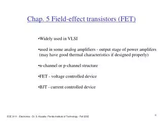
Types of Field-Effect Transistors • MOSFET (Metal-Oxide Semiconductor Field-Effect Transistor) • Primary component in high-density VLSI chips such as memories and microprocessors • JFET (Junction Field-Effect Transistor) • Finds application especially in analog and RF circuit design
The MOS Transistor Polysilicon Aluminum
n areas have been doped with donor ions (arsenic) of concentration ND - electrons are the majority carriers L Gate oxide Polysilicon Gate W Source Drain Field-Oxide (SiO2) n+ n+ p substrate p+ stopper Bulk (Body) p areas have been doped with acceptor ions (boron) of concentration NA - holes are the majority carriers The NMOS Transistor Cross Section
MOS Capacitor Structure • First electrode - Gate : Consists of low-resistivity material such as highly-doped polycrystalline silicon, aluminum or tungsten • Second electrode - Substrate or Body: n- or p-type semiconductor • Dielectric - Silicon dioxide: stable high-quality electrical insulator between gate and substrate.
Substrate Conditions for Different Biases Accumulation VG << VTN Depletion VG < VTN Inversion VG > VTN
Low-frequency C-V Characteristics for MOS Capacitor on P-type Substrate • MOS capacitance is non-linear function of voltage. • Total capacitance in any region dictated by the separation between capacitor plates. • Total capacitance modeled as series combination of fixed oxide capacitance and voltage-dependent depletion layer capacitance.
NMOS Transistor: Structure • 4 device terminals: Gate(G),Drain(D),Source(S) and Body(B). • Source and drain regions form pn junctions with substrate. • vSB, vDSand vGS always positive during normal operation. • vSB must always reverse bias the pn junctions
The Threshold Voltage VT = VT0 + (|-2F + VSB| - |-2F|) where VT0 is the threshold voltage at VSB = 0 and is mostly a function of the manufacturing process • Difference in work-function between gate and substrate material, oxide thickness, Fermi voltage, charge of impurities trapped at the surface, dosage of implanted ions, etc. VSB is the source-bulk voltage F = -Tln(NA/ni) is the Fermi potential (T = kT/q = 26mV at 300K is the thermal voltage; NA is the acceptor ion concentration; ni 1.5x1010 cm-3 at 300K is the intrinsic carrier concentration in pure silicon) = (2qsiNA)/Coxis the body-effect coefficient (impact of changes in VSB) (si=1.053x10⁻¹⁰F/m is the permittivity of silicon; Cox = ox/tox is the gate oxide capacitance with ox=3.5x10⁻¹¹F/m)
The Body Effect • VSB is the substrate bias voltage (normally positive for n-channel devices with the body tied to ground) • A negative bias causes VT to increase from 0.45V to 0.85V VT (V) VBS (V)
Concept of Asymmetric Channel • It is to be noted that the VDS measured relative to the source increases from 0 to VDS as we travel along the channel from source to drain. This is because the voltage between the gate and points along the channel decreases from VGS at the source end to VGS-VDS. • When VDS is increased to the value that reduces the voltage between the gate and channel at the drain end to Vt that is , • VGS-VDS=Vt or VDS= VGS-Vt or VDS(sat) ≥ VGS-Vt
ID n+ n+ Pinch-off - + VGS - VT Transistor in Saturation Mode Assuming VGS > VT VDS > VGS - VT VGS VDS G S D B The current remains constant (saturates).
NMOS Transistor: Saturation Region is called the saturation or pinch-off voltage
Channel-Length Modulation • As vDS increases abovevDSAT, thelength of the depleted channel beyond pinch-off point, DL, increases and actual L decreases. • iD increases slightly with vDSinstead of being constant. l = channel length modulation parameter
Enhancement-Mode PMOS Transistors: Structure • p-type source and drain regions in n-type substrate. • vGS < 0 required to create p-type inversion layer in channel region • For current flow, vGS < vTP • To maintain reverse bias on source-substrate and drain-substrate junctions, vSB < 0 and vDB < 0 • Positive bulk-source potential causes VTP to become more negative
Depletion-Mode MOSFETS • NMOS transistors with • Ion implantation process is used to form a built-in n-type channel in the device to connect source and drain by a resistive channel • Non-zero drain current for vGS = 0; negative vGS required to turn device off.
Problem-solving Technique :MOSFET DC Analysis • STep1: Requires knowing the bias condition of the transistor such as cutoff or saturation or nonsaturation. • Step2: If the bias condition is not obvious, one must guess the bias condition before analyzing the circuit. • Step3 How can we Guess? (i) Assume that the transistor is biased in the saturation region, which implies that: VGS>VTN, ID>0, and VDS≥VDS(sat) If all the above conditions are satisfied, analyze the circuit using the saturation current voltage relations. • If VGS<VTN, then transistor is probably in cutoff mode. • If VDS<VDS(sat), the transistor is likely biased in nonsaturation region, analyze the circuit using nonsaturation current voltage relations.
MOSFET Circuit Symbols • (g) and (i) are the most commonly used symbols in VLSI logic design. • MOS devices are symmetric. • In NMOS, n+ region at higher voltage is the drain. • In PMOS p+ region at lower voltage is the drain
Summary of the MOSFET Current-Voltage relationship Table 5.1