Download

1 / 38
490 likes | 1.21k Views
Condition Monitoring for Steam Turbines and Sleeve Bearing Diagnostics and Failure Analysis. Presented by: Timothy S. Irwin, P.E. Senior Mechanical Engineer M&B Engineered Solutions, Inc. 13 Aberdeen Way Elgin, SC 29045 Email: tsi@mbesi.com 17 February, 2006.

E N D
Condition Monitoring for Steam Turbines and Sleeve Bearing Diagnostics and Failure Analysis Presented by: Timothy S. Irwin, P.E. Senior Mechanical Engineer M&B Engineered Solutions, Inc. 13 Aberdeen Way Elgin, SC 29045 Email: tsi@mbesi.com 17 February, 2006
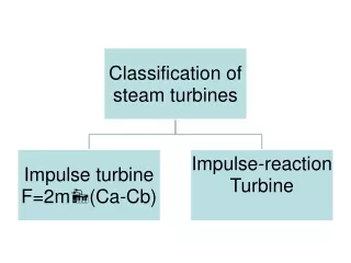
Condition Monitoring for Steam Turbines and Sleeve Bearing Diagnostics and Failure Analysis • Part I - Condition Monitoring for Steam Turbines • What is today’s definition? • We want an early warning so that when the operating condition of the turbine is changing, action can be taken to identify the failure mode. When the failure mode is properly identified, proper corrective action can be planned or taken to maintain or return the machine to reliable operation. • Part II – Sleeve Bearing Diagnostics and Failure Analysis • What is today’s definition? • Improve our understanding of sleeve bearings and their failure modes so that we can improve our monitoring techniques and failure analysis. Improvement in these areas will result in an improvement in the equipment’s performance and reliability. M&B ESI Timothy S Irwin January 2006
Part I – Condition Monitoring for Steam Turbines • To develop effective condition monitoring we need to understand a little about the machine. • What does a turbine actually do? • Steam comes in and goes out right? • The steam comes in under a certain set of pressure, temperature, and flow conditions; and goes out under another set of pressure temperature and flow conditions. • The change in steam conditions occurs because we are using some of the energy in the steam to rotate the turbine rotor. M&B ESI Timothy S Irwin January 2006
Part I – Condition Monitoring for Steam Turbines Just for a quick view, here is a decent description of a steam flow path in a multi-stage turbine: M&B ESI Timothy S Irwin January 2006 Courtesy of Power Magazine
Part I – Condition Monitoring for Steam Turbines Here is one small mechanical drive turbine. This one was actually used to drive a positive displacement oil pump. M&B ESI Timothy S Irwin January 2006
Part I – Condition Monitoring for Steam Turbines Here is another small drive turbine This one is also used to drive a positive displacement oil pump. M&B ESI Timothy S Irwin January 2006
Part I – Condition Monitoring for Steam Turbines Here is a small industrial power generation turbine. Note the mechanical layout of this machine M&B ESI Timothy S Irwin January 2006
Part I – Condition Monitoring for Steam Turbines Here is a big multi-casing utility class machine Courtesy of Power Magazine Note that a lot of the mechanical details from the smallest to the largest machines are very similar M&B ESI Timothy S Irwin January 2006
Part I – Condition Monitoring for Steam Turbines • Steam conditions and flow rate. What kind of monitoring can we do on a turbine? • Vibration. • Lubricant/bearing conditions. • Rotor speed/load or power. • Auxiliary system operation. • Noise/Sound levels. M&B ESI Timothy S Irwin January 2006
Part I – Condition Monitoring for Steam Turbines • Bearing failures from: • Loss of lubrication • Lubrication contamination • Excessive load • Blade failures: • Foreign object damage • Erosion • Fatigue What kind of failures typically occur to turbines? • Valve failures: • Solid particle damage • Erosion • Fatigue • Steam seal failures: • Wear • Erosion • Corrosion • Overspeed protection • Insulation failure • Governor/Regulation failure • Coupling failures • Hydraulic system failure • Alignment Changes M&B ESI Timothy S Irwin January 2006
Part I – Condition Monitoring for Steam Turbines Lets look a little closer at some of the failure modes. • Bearing failures can occur from: • Loss of lubrication • Lubrication contamination • Excessive load • Electrolysis • Fatigue • Wear/wiping • Faulty assembly • Corrosion • Cavitation/erosion M&B ESI Timothy S Irwin January 2006
Part I – Condition Monitoring for Steam Turbines Lets look a little closer at some of the failure modes. • Blade failures: • Foreign object damage • Can cause damage to leading edge, trailing edge, shroud, etc. • Can damage the stationary and/or rotating blades. • Erosion • Can be caused by moisture in the steam or solid particulates in the steam. • Can affect the stationary and rotating blades. • Fatigue • Will more typically affect the rotating components and typically be a catastrophic event if the condition is not identified during an inspection. M&B ESI Timothy S Irwin January 2006
Part I – Condition Monitoring for Steam Turbines • Machine Condition Discussion: • Called in to evaluate condition of machine. • Site management knew that routine maintenance had been deferred for a significant amount of time. • Could they defer further or were there indications of developing problems? • What were the results of the condition assessment? • Vibration levels were good (below 0.7 mils) using proximity probes. • Power output was down. • Steam discharge conditions were at saturated steam conditions. • Steam leakage at shaft seals was excessive, causing constant moisture contamination in the lube oil system. M&B ESI Timothy S Irwin January 2006 My recommendation was not to defer the overhaul.
Part I – Condition Monitoring for Steam Turbines • Blade failure/damage: M&B ESI Timothy S Irwin January 2006
Part I – Condition Monitoring for Steam Turbines • Blade failure/damage: M&B ESI Timothy S Irwin January 2006
Part I – Condition Monitoring for Steam Turbines • Blade failure/damage: M&B ESI Timothy S Irwin January 2006
Part I – Condition Monitoring for Steam Turbines • Valve failures: What happens to valves? • Erosion of the plug • Erosion of the seat • Corrosion of the spindle or stem • Galling of the spindle or stem in the guide bushings or bearings. • Wear of the guide bushings or bearings • Wear of the linkage components The steam admission valve or stop valve or emergency stop valve is part of the equipment protection! M&B ESI Timothy S Irwin January 2006
Part I – Condition Monitoring for Steam Turbines • Steam Seal failures: What happens to steam seals? • Larger machines with actual seal strips (labyrinth seals) • Wear of the seal tip height • Corrosion of the mating surfaces • Corrosion of the segments and housing. • Corrosion and failure of segment springs • Smaller machines with carbon seal rings • Wear of the carbon rings • Wear of the shaft surface • Corrosion and wear of the housing faces. M&B ESI Timothy S Irwin January 2006
Part I – Condition Monitoring for Steam Turbines • Steam Seal failures: What happens to steam seals? M&B ESI Timothy S Irwin January 2006
Part I – Condition Monitoring for Steam Turbines • Steam Seal failures: What happens to steam seals? M&B ESI Timothy S Irwin January 2006
Part I – Condition Monitoring for Steam Turbines • Alignment Definition – What does alignment mean to ‘coupled’ rotating machines? In short – we are looking for the two (or more) shaft centerlines to be concentric to each other. If the shaft centerlines are not concentric to each other, then the shafts through the coupling try to force themselves together. Depending on the coupling type, this ‘aligning’ force may show Itself as various ‘vibration signature changes or indications’, or if severe enough bearing temperatures or conditions may be affected. What can cause misalignment? • Misalignment at installation or refurbishment • Thermal growth changes • Piping strain • Sleeve bearing damage M&B ESI Timothy S Irwin January 2006
Part I – Condition Monitoring for Steam Turbines • Alignment Definition – What does alignment internal to a single machine mean? In short – We want to have the shaft/rotor within a certain position relative to the casing. Some machines behave better with the rotor not centered in the casing. Some machines behave better with the rotor centered. A very typical indication is a ‘rub’ condition in the vibration data. What can cause misalignment? Basically the same conditions apply to internal and external misalignment. • Misalignment at installation or refurbishment • Thermal growth changes • Piping strain • Sleeve bearing damage M&B ESI Timothy S Irwin January 2006
Part I – Condition Monitoring for Steam Turbines Remaining failure modes: • Overspeed protection • Sticking bolt • Worn linkage • Incorrect electronic settings • Insulation failure • Air gaps • It has become wet • Pieces are missing • Incorrect installation • Governor/Regulation failure • Worn parts • Contaminated system • Coupling failures • Lubrication failure • Wear • Fatigue • Hydraulic system failure • Worn components • Contaminated system M&B ESI Timothy S Irwin January 2006
Part I – Condition Monitoring for Steam Turbines Failure modes and monitoring methods: We have to perform the following: • Realistically determine the most appropriate uses of the available tools. • Determine the realistic limits of the monitoring tools. • Determine what we cannot measure or monitor. • Determine what is appropriate per piece of equipment. M&B ESI Timothy S Irwin January 2006
Part I – Condition Monitoring for Steam Turbines • Steam conditions and flow rate. What kind of monitoring can we do on a turbine? • Vibration. • Lubricant/lubrication conditions. • Rotor speed/load or power. • Auxiliary system operation. • Noise/Sound levels. M&B ESI Timothy S Irwin January 2006
Part I – Condition Monitoring for Steam Turbines Steam Conditions – What kind of readings do we want to take? Depends on the machine, what kind of readings do we have available or can we take? • Is it a small machine with little instrumentation or is it a large • machine with a considerable amount of instrumentation? • Minimal measurements would be temperature and pressure • upstream and downstream of the turbine. • If you can include flow, power, inlet chamber pressure you will • know a considerable amount about the ‘power’ characteristics of the • turbine. • Look for: • A change in downstream conditions from what is normal. • It could be an increase in downstream pressure • Also understand what the ‘design conditions’ may mean • (i.e. get a copy of some steam tables) M&B ESI Timothy S Irwin January 2006
Part I – Condition Monitoring for Steam Turbines Steam Tables Mechanical Engineering Reference Manual – Michael R. Lindeburg M&B ESI Timothy S Irwin January 2006
Part I – Condition Monitoring for Steam Turbines Vibration – What kind of readings do we want to take? Depends on the machine. • If it is a small machine • Is it a sleeve bearing, anti-friction bearing, or combination machine? • Mag-based accelerometers are going to be severely limited with • sleeve bearing machines. But smaller horsepower machines are not • going to typically have proximity probes installed unless the machine • is very critical to the process. • What kind of data are we going to see on sleeve bearing machines • using mag-based accelerometers? M&B ESI Timothy S Irwin January 2006
Part I – Condition Monitoring for Steam Turbines What data do I want? • PdM Routes • For vibration: • Horizontal and vertical on each bearing. • Locate the thrust bearing and take an axial reading. Also include a speed reading if at all possible. What are we looking for? • Vibration • Changes • Running speed multiples • Increase in 1X • Increase in noise floor Has the speed changed? M&B ESI Timothy S Irwin January 2006
Part I – Condition Monitoring for Steam Turbines For larger machines with installed shaft vibration monitors: Compare the shaft data to casing data. • How do those data sets compare? • Are they at different amplitude levels, but similar characteristics? • Are they different characteristics? • Multiples on the casing, not on the shaft data? • Different noise floor levels? • Different phase indications? • Does the orbit shape generally agree with where you see higher • vibration levels on the casing? Remember, we are looking for changes. Having absolute limits for operation and equipment protection is one thing, but all the monitoring instruments calculate vibration levels slightly differently. In the field, it is hard to have an absolute anything. M&B ESI Timothy S Irwin January 2006
Part I – Condition Monitoring for Steam Turbines Again, what kind of machine do we have? Large or small? Lubrication /lubricant conditions • If it is big enough to have a sump, then we can perform typical • oil analysis testing. • Viscosity, water, particulates, and spectrographic for routine • Monitoring. • If it is not big enough for sump but uses ‘oilers’ to ensure an oil supply for the bearing housing there are still things that need to be correct for a machine to achieve a reasonable time between repairs. • Oil level in the oiler. • Oil level in the bearing housing. • Oil color in the oiler. • Inspect the housing cavity for typical indications of contamination or condition during routine overhauls. M&B ESI Timothy S Irwin January 2006
Part I – Condition Monitoring for Steam Turbines Lubrication /lubricant conditions What are we looking for in an oil analysis? There are three major condition groups that oil analysis can monitor: • Oil Condition • Viscosity • Additive packages • Oil Contamination • Moisture • Particulates • Equipment Condition • Wear particles • Material or source • Ferrography M&B ESI Timothy S Irwin January 2006
Part I – Condition Monitoring for Steam Turbines Rotor speed/load or power. • Is there any permanent monitoring available? • Load • Speed • If no permanent monitoring is available, is there anything else you can use to verify operating load? • Is a place on the shaft available for an optical or laser tachometer? • Is the process controlled by inlet or discharge valves? • Are there any flow indications? These items become even more critical for a variable load process! M&B ESI Timothy S Irwin January 2006
Part I – Condition Monitoring for Steam Turbines Auxiliary System Operation. On larger machines, there are considerable auxiliary systems that may also indicate development of a significant issue. • Gland steam or Seal steam systems • Shaft leakage increased • More use of steam • Changing pressure conditions • Hydrogen seal oil systems • Higher flow rates from increased shaft leakage • Hydrogen purity issues • Changing pressure conditions • Cooling water conditions • Conductivity • Flow or pressure changes M&B ESI Timothy S Irwin January 2006
Part I – Condition Monitoring for Steam Turbines Auxiliary System Operation. On larger machines, there are considerable auxiliary systems that may also indicate development of a significant issue. • Condenser conditions • Vacuum pressure changes • Condensate temperature changes • Air in-leakage changes • Feedwater Heater conditions • Steam inlet/outlet condition changes • Condensate inlet/outlet condition changes M&B ESI Timothy S Irwin January 2006
Part I – Condition Monitoring for Steam Turbines Noise/Sound levels. With modern ultrasound technologies, it should be possible to monitor and trend changing conditions within these machines. We should be able to monitor the following: • Valve conditions at known positions, especially when closed • Turbine noise levels at known conditions • Bearing noise levels at known conditions M&B ESI Timothy S Irwin January 2006
Part I – Condition Monitoring for Steam Turbines Summary There are considerable technologies that are available for use However, the tools we have discussed today are only several pieces of an overall reliability program. Preventive, Predictive, and Proactive or Reliability Centered components are all necessary to improve reliability and minimize overall operational cost. Basically, the more we know about the machine, the better we can diagnose a changing condition. M&B ESI Timothy S Irwin January 2006
Part I – Condition Monitoring for Steam Turbines THE END ANY QUESTIONS? M&B ESI Timothy S Irwin January 2006