Download
1 / 32
360 likes | 1.06k Views
Compressor technology. Barrel. Horizontal Split. Pipeliner - Axial Inlet. Pipeliner - Horizontally Opposed Flanges. Centrifugal compressor. 26/03/99. 009662/01 PPT. Compressor experience. Installed or on order Pipeline Centrifugal 835 Multi-Stage Centrifugal 687

E N D
Barrel Horizontal Split Pipeliner - Axial Inlet Pipeliner - Horizontally Opposed Flanges Centrifugal compressor 26/03/99 009662/01 PPT
Compressor experience Installed or on order Pipeline Centrifugal 835 Multi-Stage Centrifugal 687 Total Achievement1522 26/03/99 009661/02 PPT
Multi-Stage barrel centrifugal compressors Over 480 sold since 1957 Vertical split barrel-type design Designed for a broad range of oil and gas applications Four frame sizes Standard impeller selections for performance predictability Maximum working pressure up to 450 bar Suitable for direct-drive by Cooper Rolls/Allison gas turbines, without the need for a gearbox Uses same lube oil as power turbines - no requirement for separate oil systems 26/03/99 009661/01 PPT
Multi-Stage barrel compressors • Full range of hydrocarbon gases • High pressure ratio/head capability • Up to highest operating pressures • Cast/forged steel casings • Custom casing design within established frame sizes 26/03/99 009661/03 PPT
RBB RCB RDB REB Maximum Pressure Rating [BAR] 450 230 150 83 [PSIG] 6500 3200 2200 1200 Number of Stages 1 – 8 1 – 8 1 – 8 1 – 8 [m³/h] Max. Design Inlet Flow 10200 23000 37500 60000 [ACFM] 6000 13500 22000 35,300 Max. Running Speed [RPM] 14550 11000 7850 6500 Standard Impeller Diameters [mm]/[IN] 351 / 13.75 521 / 20.5 673 / 26.5 864 / 34.0 381 / 15.0 559 / 22.0 711 / 28.0 419 / 16.5 Active barrel compressor frame sizes 26/03/99 009661/07 PPT
Multi-Stage barrel compressors 26/03/99 009661/08 PPT
Front-to-Back Back-to-Back Multi-Stage centrifugal impeller arrangements 26/03/99 009661/05 PPT
Barrel and horizontally split combination 26/03/99 009662/02 PPT
Pipeline compressors Over 800 sold since 1955 Seven different models suitable for direct-drive by Cooper Rolls Gas Turbines Tilt-pad journal and thrust bearings Designed to API 617 Dry gas seals Up to five impellers Uses same lube oil as power turbine, no requirement for separate oil system Choice of axial inlet or opposed-flange casings 26/03/99 009661/09 PPT
Pipeline compressor types • Conventional • Horizontally opposed nozzles/side inlet • Beam-style (and overhung) rotor designs • Wide pressure ratio/head flexibility - up to five stages • High aerodynamic efficiencies • Fixed casing design per frame size • Fixed pressure ratings up to 155 bar • Axial inlet • Highest aerodynamic efficiencies: Near 90% isentropic • Limited to single-stage designs • Overhung rotor design • Pressures up to 125 bar • Fixed casing design per frame size 26/03/99 009663/01 PPT
Active pipeline booster frame sizes RC14RF20RF30RF36RF42RFA24RFA36 Nozzle Arrangement Side Inlet Side Inlet Side Inlet Side Inlet Side Inlet Axial Inlet Axial Inlet Bearing Arrangement O’Hung Beam O’Hung O’Hung O’Hung O’Hung O’Hung & Beam & Beam & Beam & Beam Number of Stages 1 - 3 1 - 4 1 - 4 1 - 4 1 - 5 1 1 Max. Casing Rating [BAR] 105 105 100 95/155 105 103 105/125 [PSIG] 1500 1500 1440 1380/2250 1500 1500 1500/1800 Max. Design Inlet Flow [m³/h] 11300 22000 52300 77000 107000 43000 103000 [ACFM] 6640 13000 30800 45400 62800 25300 60500 Max. Operating Speed [RPM] 14500 14500 7000 7000 7000 14500 7000 Max. Impeller Diameter [mm] 495/457 660/533 1230/1050 1230/1050 1230/1050 710 1230 [INCH] 19.5/18 26/21 48.5/41.5 48.5/41.5 48.5/41.5 28.0 48.5 26/03/99 009661/06 PPT
Pipeline centrifugal compressors 26/03/99 009661/10 PPT
Pipeliner cross section 26/03/99 009659/02 PPT
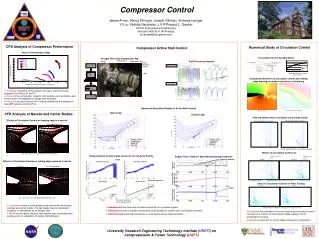
Typical RFA 36 pipeline booster performance map 26/03/99 009663/05 PPT
Fluid film tilting pad bearings • Rotor supported by a hydrodynamic pressurized • oil film generated between the rotor & white metal • lined bearing pads • Well established & accepted technology • Compact cartridge design • High stiffness & damping capabilities • High load capacities • High reserve capacities - Resistant to upsets • Requires complex oil supply & control system 26/03/99 009665/05 PPT
Shaft sealing technologies • Bushing Seals: Principle: Injection of regulated high pressure oil between two • adjacent cylindrical white metal / aluminum lined • rings at each end of compressor • Config’s: - Single breakdown seals up to ~ 140 bar • - Double breakdown seals for higher pressures • Dry Gas Seals: Principle: Use cleaned & dried process gas at discharge • pressure bleeding across highly polished & • profiled radial faces separated by very small • clearances • Config’s: - Tandem seal with second stage as safety • back-up • - Triple seal required above 140 bar 26/03/99 009665/01 PPT
Dry gas seals • Advantages Oil Free • Simple, low maintenance control system • Limitations Tandem seals limited to 140 bar • No rotor damping • Limited axial travel • Requires clean & dry sealing gas • Sensitive to lube oil migration - Requires buffer • air and barrier seal • Complex design • No on-site maintenance • Requires high installation skill • Sticking problems • High cartridge cost 26/03/99 009665/04 PPT
Carbon Faces (Stationary) Primary Rings (Rotating) Tandem dry gas face seal 26/03/99 009665/03 PPT
Active magnetic bearings • Magnetic Rotor supported by electromagnetic fields • Requires significant air cooling for power outages • Requires auxiliary bearings • Promising technology - Fairly new to large • industrial turbo machinery (1988) • Large bearing dimensions • Reduced stiffness & damping capabilities • Limited load capacities • Limited reserve capacities - Easy to upset • Requires complex digital control system • Requires careful system tuning 26/03/99 009665/06 PPT
Magnetic and auxiliary journal bearings Magnetic and auxiliary journal bearings Magnetic and auxiliary journal bearings 26/03/99 009665/09 PPT
RF2BB30 with magnetic bearings 26/03/99 009665/07 PPT
Inlet guide vanes 26/03/99 009664/01 PPT
Inlet guide vane performance 26/03/99 009664/03 PPT
Compressor running testsAerodynamic performance • Type of test Purpose • • Modified ASME PTC 10 Class 3: • Performance Validation - Typical on Pipeline Compressors • • Full ASME PTC 10 Class 3: • Performance Validation - All Compressors • • Full ASME PTC 10 Class 1: • Performance Validation on High Pressure Multistage Compressors • • Confirmation of Rotor Stability • • Absence of Rotating Stall 26/03/99 009668/05 PPT
Compressor running testsMechanical and rotordynamic performance • Type of test Purpose • • Standard API-617 Mechanical: • Confirmation of Mechanical Performance - All Compressors • • Full Density & Speed String: • Confirmation of Mechanical Performance - High Pressure Multistage Compressors • • Confirmation of Rotor Stability • Absence of Rotating Stall • • Full ASME PTC 10 Class 1 String: • Same as Above 26/03/99 009668/06 PPT
Major compressor development programs • Continuous Stage Efficiency Improvement • Allison Compressor Frame Size Development • Cycle Time Cost Reduction 26/03/99 009668/01 PPT
Compressor stage efficiency improvement • Development Plan • Select / develop new advanced aerodynamic design software • Calibrate the new software with development testing • Perform parametric studies necessary to define basic stage geometry • Redesign both barrel and pipeline compressor families as • necessary to upgrade performance • Populate each family with standard designs 26/03/99 009668/02 PPT
Compressors for the CR-501 and CR-601 • RCBB-14RFBB-20RFA-24RBB • Flange Size, in. 14 20 24 6-12 • No. Stages 1-3 1-4 1 1-8 • Max. Power 7500 15000 18000 35000 • Design Speed 9000-13800 9000-11500 9000-13800 9000-13800 • Max. Design Point • Flow (ACFM) 6640 13000 25300 6000 • (m3/h) 11300 22000 43000 10200 • Optimum Eff’cy 83-85% 83-85% 86-88% 78-80% • Typical Driver 501-KC5 601-KC9 501-KC5 501-KC5 • 501-KC7 601-KC11 501-KC7 501-KC7 • 601-KC9 601-KC9 • 601-KC11 601-KC11 • MWP, psig 1500 1500 1500 4000 • bar 105 105 105 275 26/03/99 009668/03 PPT
Cycle time and cost reduction • Lead time • Objective: Start 1-Jan-98 100% • Target 65% • Measures: • Improved Engineering Tools • Rationalization of Supplier Base • Expansion of Manufacturing Cells concept to all • components • Improved Fabrication & Packaging Techniques 26/03/99 009668/04 PPT
Summary • 50 years of experience in centrifugal compressors • Concentration on oil and gas applications since 1972 • Broad model range for all natural gas applications • High, field-proven efficiency and dependability • Single to multiple unit trains, gas turbine or motor driven • (including variable speed motors up to 30MW) • Early introduction and leadership in the use of advanced shaft • sealing and bearing technology, eg • - more than 200 compressors with dry gas seals since 1985 • - 24 pipeline compressors with active magnetic bearings • - 5 to 25MW, 8500 to 5000 rpm • State-of-the-art fabrication, testing and packaging techniques • Compliance with all major international technical standards 26/03/99 009668/07 PPT
End of Compressor technologyPlease press “Esc” to return to main menu