Download
1 / 42
440 likes | 574 Views
Logic Functions. OR Operation A coil is not energized until either normally open switch A or B is closed. . Boolean Logic Diagram. Logic Functions. NOR Operation There has to be an output when neither A nor B has input. When there is input to A or B the output ceases. .

E N D
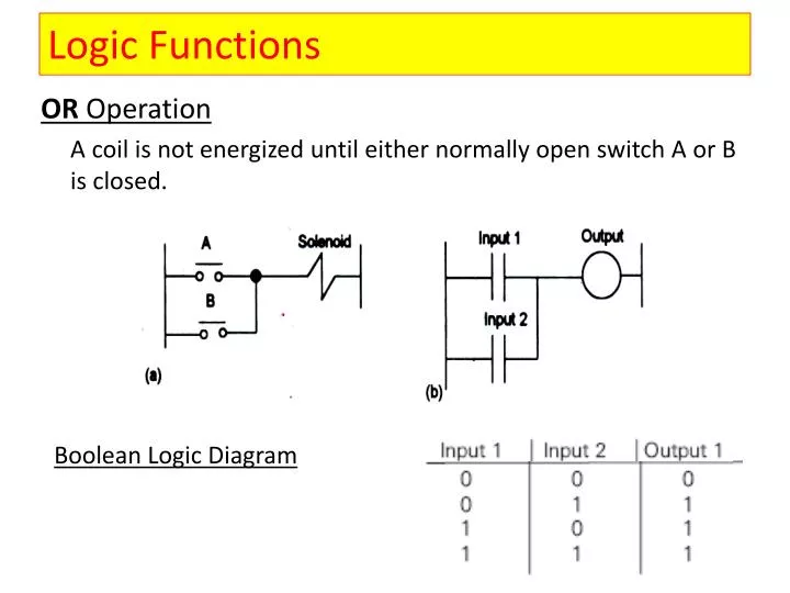
Logic Functions OR Operation A coil is not energized until either normally open switch A or B is closed. Boolean Logic Diagram
Logic Functions NOR Operation There has to be an output when neither A nor B has input. When there is input to A or B the output ceases.
Logic Functions NANDOperation • There is no output when both A and B have an input.
Logic Functions EXCLUSIVE-OR (XOR)Operation No output when the status of the inputs is same No output when there is no input to both Input 1 and 2 and when there is an input to both Input 1 and Input 2
Testing a Program Through Simulation Status Functions
Testing a Program Through Simulation Forcing Used to temporarily override the input or output status of the application in order to test and debug the program
Case Study -1 Discrete Inputs/Outputs Wiring
Case Study – 1 contd… Discrete Inputs/Outputs
Case Study - 2 Motor starter to control a three-phase AC motor: Hard-wired Approach
Case Study – 2 contd… Motor Starter – Hard-wired Approach Momentarily depressing the Start pushbutton completes the path of current flow and energizes the motor starter (M).
Case Study – 2 contd… Motor Starter – PLC Approach
Case Study – 2 contd… Motor Starter – PLC Approach
Case Study – 2 contd… Motor Starter – PLC Approach When Start pushbutton is pressed, the CPU receives a logic 1 from input I0.0. This causes the I0.0 contact to close. All three inputs are now a logic 1. The CPU sends a logic 1 to output Q0.0. The motor starter is energized and the motor starts.
Case Study – 2 contd… Motor Starter – PLC Approach The output status bit for Q0.0 is now a 1. On the next scan, when normally open contact Q0.0 is encountered, the contact will close and output Q0.0 will stay on even if the Start pushbutton is released.
Case Study – 2 contd… Motor Starter – PLC Approach When the Stop pushbutton is pressed, input I0.1 turns off, the I0.1 contact opens, output coil Q0.0 de-energizes, and the motor turns off.
Case Study – 2 contd… Expanding the Application - Run & Stop Indicators Lamps
Case Study – 2 contd… Expanding the Application - Run & Stop Indicators Lamps When Q0.0 is off, the normally open Q0.0 contact on Network 2 is open and the RUN indicator off. At the same time, the normally closed Q0,0 contact is closed and the STOP indicator is on.
Case Study – 2 contd… Expanding the Application - Run & Stop Indicators Lamps Start button is pressed, output Q0.0 is on. The normally open Q0.0 contact on Network 2 is closed and the RUN indicator on. The normally closed Q0.0 contact on Network 3 is open and the STOP indicator light connected to output Q0.2 is off.
Case Study – 2 contd… Adding a Limit Switch A limit switch could be used to stop the motor or prevent the motor from being started.
Case Study – 2 contd… Adding a Limit Switch If the access door is open, the normally open contacts of LS1 connected to input I0.3 are open and the motor will not start.
Case Study – 2 contd… Adding a Limit Switch When the access door closes, LS1 closes. Input I0.3 is now on, and the motor will start when the Start pushbutton is pressed.
Case Study – 2 contd… Further Expansion
Analog Inputs Application Example
Analog Inputs Expanding the Application – A Conveyor System • As packages move along the conveyor, they are weighed. • A package that weighs at or greater than a specified value is routed along one conveyor path. • A package that weighs less than a specified value is routed along another conveyor path, where it will later be inspected for missing contents.
Analog Outputs • The transducer takes the voltage signal • Depending on the requirement, amplifies, reduces, or changes it into another signal which controls the device. • The 0 - 10 VDC signal controls the 0 - 500 Lbs. scale analog meter
Timers • Timers are devices that count increments of time • The output of the timer is a logic 0 as long as the current time is less than the preset time. • When the current time is greater than the preset time, the timer output is a logic 1
Timers Hard-Wired Timing Circuit (On-delay) • When S1 closes, TR1 begins timing. • When 5 seconds (preset) have elapsed, TR1 will close its associated normally open TR1 contacts, illuminating pilot light PL1. • When S1 opens, de-energizing TR1, the TR1 contacts open, immediately extinguishing PL1.
Timers On-Delay Timer (TON) • When the On-Delay Timer (TON) receives an enable (logic 1) at its input (IN), a predetermined amount of time (preset time - PT) passes before the timer bit (T-bit) turns on. • The timer resets to the accumulated time to zero when the enabling input goes to a logic 0.
Timers Example A switch is connected to input I0.3, and a light is connected to output Q0.1. If the switch were opened before 15 seconds has passed, then re-closed, the timer would again begin timing at 0. Because this type of timer does not retain its accumulated time when its input (IN) goes to logic 0, it is said to be non-retentive.
Timers T37 is now a normally closed contact. What is the function of this circuit now? Function: Causes the indicator light to turn off only when the timer times out
Timers Retentive On-Delay Timer (TONR) Just like the On-Delay timer (TON), the Retentive On-Delay Timer (TONR) times as long as the enabling input is on, but does not reset when the input goes off.
Timers Example • If, for example, after 10 seconds input I0.3 turns off, the timer stops. • When input I0.3 turns on again, the timer begins timing at 10 seconds. • The light connected to Q0.1 turns on 5 seconds after input I0.3 has been closed for the second time.
Timers Off-Delay Timer Used to delay turning an output off for a fixed period of time after the input turns off When the enabling bit turns on, the timer bit turns on immediately, and the time value is set to 0. When the input turns off, the timer times until the preset time has elapsed. At that time, the timer bit turns off.
Timers Timer Example A tank is filled with two chemicals, the solution is mixed, and the tank is drained.
Timers Steps • When the Start button is pressed, input I0.0 turns on, and the program starts pump 1, controlled by output Q0.0. Pump 1 runs for 5 seconds, adding the first chemical to the tank, then shuts off. • The program then starts pump 2, controlled by output Q0.1. Pump 2 runs for 3 seconds adding the second chemical to the tank. After 3 seconds pump 2 shuts off. • The program then starts the mixer motor, connected to output Q0.2 and mixes the two chemicals for 60 seconds. • Next, the program opens the drain valve, controlled by output Q0.3, and starts pump 3 controlled by output Q0.4. Pump 3 shuts off after 8 seconds and the process stops.
Counters • Counters compare an accumulated value to a preset value to control circuit functions. • Used to initiate an operation when a count is reached or to prevent an operation from occurring until a count has been reached.
Counters Count Up Counter (CTU) • Counts up from the current value each time the count up (CU) input goes from off to on. • When the current value is greater than or equal to the preset value (PV), the counter bit is a logic 1. • The course resets when the reset (R) input turns on. The counter stops counting when it reaches its maximum value of 32,767.
Counters Count Down Counter (CTD) • Counts down from the current value each time the count down (CD) input goes from off to on. • When the current value is equal to zero, the counter bit is a logic 1. The counter stops counting at zero. • The counter resets and loads the current value with the preset value (PV) when the load input (LD) turns on.