Download
1 / 30
300 likes | 409 Views
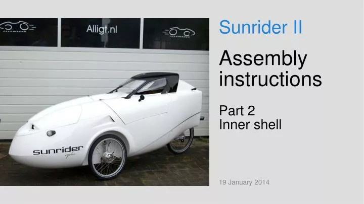
Sunrider II. Assembly instructions Part 2 Inner shell. 19 January 2014. Contents part 2 Sec. Subject Slide 2/1 Attachment point joy-stick 2/2 Aluminium rear frame 2/3 Preparations on inner shell 2/4 Seat attachment point. 2/1. Attachment point steering joy-stick. Parts.

E N D
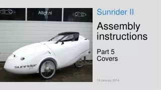
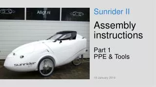
Sunrider II Assembly instructionsPart 2Inner shell 19 January 2014
Contents part 2 Sec. Subject Slide 2/1 Attachment point joy-stick 2/2 Aluminium rear frame 2/3 Preparations on inner shell 2/4 Seat attachment point
Parts. Tools.
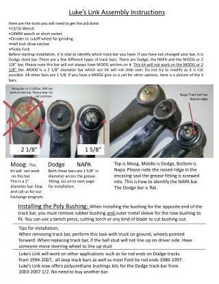
Prepare:Tape inner shell to prevent damage Showing the fixation of the attachment point on the inner shell.
Flatten and grind the bonding surfaces briefly. Remove dust thoroughly.
Place marks for 3 drilling holes 3 holes by 6 mm drill .
Add a little kit on the inside. Push the aluminium inside-part into the kit. Align the bolt holes.
Add some Loctite on the bolts. Add a little kit on the aluminium outer part and screw the parts together.
Add kit. Bond joy-stick attachment point on inner shell and push against stop-points, see arrows.
Too much kit used. As such, this is not a problem but superfluous use of kit results too heavy Sunrider. Bottom fixing. Note use of pieces of sandpaper to prevent slipping.
Fixing with adhesive tape along back of inner shell. Fixing with adhesive tape around inner shell.
Bar L = 495 mm between wheel arches to realize right sizing.Harden kit for at least 24 hours at room temperature.
After curing, remove the fixation materials and add kit along the outer edges of the joy-stick fixation point.
Place outer shell in assembly templateSand mounting surface.Apply 2 outer fixation bolts. Apply kit on aluminium rear frame and push it into place.
Tighten the outer bolts lightly (hand tight). Avoid to press too much kit away. A thin layer of kit shall remain between aluminium rear frame and outer shell. Bolts are applied through the assembly template.
Smooth off the Kit around aluminium rear frame. Clean the aluminium surface well with a little benzene. Apply two dots of kit just above the aluminium rear frame , on the surface above the nod.
The inner shell comes with markings for drilling holes and cuts.
Drill 4 holes 8 mm in center console and make a rectangular hole using a 'cats tail ‘ file.
- Drill 25 mm holes using a hole saw, for the chain throughput slots.- Apply cutting marks.- Cut the slots along the cutting marks using a multi-saw.
Drill holes using 25 mm hole saw on corners of:- joy-stick slots.- recess for dashboard . Cut slots and recess using a multi-saw and finish the cuts with file and sandpaper.
Drill 4 holes 8 mm in bulkhead, to make square hole for bar that is used for fixation of crankshaft. Make square hole with ‘cats tail’ file, to fit bar.
Cut bulkhead and sides of inner shell to size, along markings. The black markings shall be cut away just.
Same for markings at rear end of inner shell. Prepared inner shell.
Parts for attachment point. All parts installed. - Large washers are installed facing the inner shell. - It may require some force to screw the long bolt in the thread of the attachment point . It will be more easy following this first try.
Sand the surface under the attachment point. Apply kit on the inner-side of the attachment point.
Apply kit under shown washers. Installed attachment point. – Fill the remaining space between inner shell and attachment point with kit and smoothen it. - Take care not to tighten the shown bolts too much. It may result cracks in the gel coat of the inner shell. As such, it’s not a bad thing when this happens but it doesn’t look nice.