Download
1 / 65
680 likes | 927 Views
CSC 830 Computer Graphics Lecture 5 Shading. Course Note Credit: Some of slides are extracted from the course notes of prof. Mathieu Desburn (USC) and prof. Han-Wei Shen (Ohio State University). Shading. Determining the light traveling from a point in the scene to the viewer’s eye.

E N D
CSC 830 Computer GraphicsLecture 5Shading Course Note Credit: Some of slides are extracted from the course notes of prof. Mathieu Desburn (USC) and prof. Han-Wei Shen (Ohio State University).
Shading Determining the light traveling from a point in the scene to the viewer’s eye Images courtesy of Watt, Watt & Watt, and Foley & van Dam
Shading Light comes from many sources: reflection scattering absorption transmission emission
Local versus Global Illumination • Global Illumination • Considers indirect illumination • Reflection • Refraction • Shadows • Local Illumination • Only considers direct illumination • No reflection • No refraction • Shadows possible
Local versus Global Illumination Direct Illumination Indirect Illumination We will do local only for this lecture…
Local illumination • Only consider the light, the observer position, and the object material properties
Local versus Global Illumination Images courtesy of Francois Sillion To understand shading properly, we need to review some basic notions of physics…
Basic Illumination Model • Simple and fast method for calculating surface intensity at a given point • Lighting calculation are based on: • The background lighting conditions • The light source specification: color, position • Optical properties of surfaces: • Glossy OR matte • Opaque OR transparent (control refection and absorption)
Radiance Radiance: Power per unit projected area perpendicular to the ray, per unit solid angle in the direction of the ray Think of it as a flux of photons leaving the surface…
Irradiance Irradiance: Radiant energy per unit area Think of it as a flux of photons bombarding the surface…
BRDF Bidirectional Reflection Distribution Function Determines the fraction of light from an incoming direction reflected to an outgoing direction Relates reflected radiance to incoming irradiance… Image courtesy of Watt, 3D Computer Graphics
Properties of the BRDF Reciprocity In photography and holography, reciprocity refers to the relationship between the intensity of the light and duration of the exposure that result in identical exposure. Within the normal range for intensity and time for the film, the reciprocity law states that exposure = intensity × time. Outside the normal range the reciprocity law breaks down, which is known as reciprocity failure.
Properties of the BRDF Anisotropy Anisotropy (the opposite of isotropy) is the property of being directionally dependent. In the field of computer graphics, an anisotropic surface will change in appearance as it is rotated about its geometric normal, as is the case with velvet. Anisotropic scaling occurs when something is scaled by different amounts in different directions.
Reflectance Equation BRDF allows us to calculate outgoing light, given incoming light Image courtesy of Watt, 3D Computer Graphics
Splitting the BRDF In practice, BRDF can be really funky…To simplify, we divide the BRDF into 3 components:
Reflectance • 3 forms Slide Courtesy of Dutre et. al on SIGGRAPH 2001
Ideal Specular Reflection Reflection is only in the mirror direction
Ideal Diffuse Reflection Reflection is equal in all directions
Directional Diffuse Reflection Reflection is concentrated around the mirror direction
Ambient Light If a surface is visible from the eye, but not a light, it will be rendered black (if indirect light is not considered). • Ambient light is an approximation to indirect light • Difficult to compute • Approximate this as a constant • Or a light source at the eye
Phong Reflection Assume point lights and direct illumination only
Diffuse Light • The illumination that a surface receives from a light source and reflects equally in all directions • This type of reflection is called Lambertian Reflection (thus, Lambertian surfaces) • The brightness of the surface is indepenent of the observer position (since the light is reflected in all direction equally)
Lambert’s Law • How much light the surface receives from a light source depends on the angle between its angle and the vector from the surface point to the light (light vector) • Lambert’s law: the radiant energy ’Id’ from a small surface da for a given light source is: Id = IL * cos(q) IL : the intensity of the light source • is the angle between the surface normal (N) and light vector (L)
Phong Diffuse Component Diffuse component depends only on incident angle. Note: L and N are unit… Image courtesy of Watt, 3D Computer Graphics
Examples Sphere diffusely lighted from various angles !
Specular Light • These are the bright spots on objects (such as polished metal, apple ...) • Light reflected from the surface unequally to all directions. • The result of near total reflection of the incident light in a concentrated region around the specular reflection angle
Specular Highlights • Shiny surfaces change appearance when viewpoint is changed • Specularities are caused by microscopically smooth surfaces. • A mirror is a perfect specular reflector
Phong Specular Component Phong combines directional diffuse & ideal specular Image courtesy of Watt, 3D Computer Graphics
Half Vector • An alternative way of computing phong lighting is: Is = ks * Is * (N*H)n • H (halfway vector): halfway between V and L: (V+L)/2 • Fuzzier highlight • Check http://www.lighthouse3d.com/opengl/glsl/index.php?ogldir2 N H L V
Phong Illumination Moving Light Change n
Phong Ambient Component Treat it as a constant: Where is the ambient light in the scene.
Phong Reflection Image courtesy of Watt, 3D Computer Graphics
OpenGL Materials GLfloat white8[] = {.8, .8, .8, 1.}, white2 = {.2,.2,.2,1.},black={0.,0.,0.}; GLfloat mat_shininess[] = {50.}; /* Phong exponent */ glMaterialfv( GL_FRONT_AND_BACK, GL_AMBIENT, black); glMaterialfv( GL_FRONT_AND_BACK, GL_DIFFUSE, white8); glMaterialfv( GL_FRONT_AND_BACK, GL_SPECULAR, white2); glMaterialfv( GL_FRONT_AND_BACK, GL_SHININESS, mat_shininess);
OpenGL Lighting GLfloat white[] = {1., 1., 1., 1.}; GLfloat light0_position[] = {1., 1., 5., 0.}; /* directional light (w=0) */ glLightfv(GL_LIGHT0, GL_POSITION, light0_position); glLightfv(GL_LIGHT0, GL_DIFFUSE, white); glLightfv(GL_LIGHT0, GL_SPECULAR, white); glEnable(GL_LIGHT0); glEnable(GL_NORMALIZE); /* normalize normal vectors */ glLightModeli(GL_LIGHT_MODEL_TWO_SIDE, GL_TRUE);/* two-sided lighting*/ glEnable(GL_LIGHTING);
Vertex Normals vs. Face Normals What are the normals to the surface? Each polygonal face has a normal. c N = (b - a) x (c - b) a b We call these face normals.
Flat Shading Assume a constant color across the polygon c a b Uses face normals Equivalent to single point sampling… Polygon mesh is only an approximation. Can we do better?
Vertex Normals vs. Face Normals Should use the actual surface’s normals Usually stored at the vertices of the object Can calculate as averages of face normals
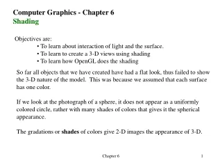
Shading Models for Polygons • Constant Shading (flat shading) • Compute illumination at any one point on the surface. Use face or one normal from a pair of edges. Good for far away light and viewer or if facets approximate surface well. • Per-Pixel Shading • Compute illumination at every point on the surface. • Interpolated Shading • Compute illumination at vertices and interpolate color
Interpolation Given vertex normals, how to color the interior: • Gouraud Interpolation • Phong Interpolation