Download
1 / 26
260 likes | 462 Views
ECE232: Hardware Organization and Design. Part 2: Datapath Design – Binary Numbers and Adders http://www.ecs.umass.edu/ece/ece232/. Computer Organization. 5 classic components of any computer Today we will look at datapaths ( adder, multiplier, … ). Computer. Processor (CPU). Memory.

E N D
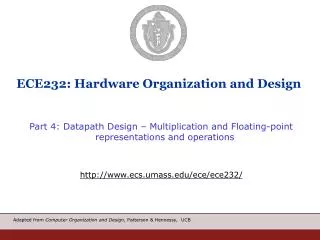
ECE232: Hardware Organization and Design Part 2: Datapath Design – Binary Numbers and Adders http://www.ecs.umass.edu/ece/ece232/
Computer Organization • 5 classic components of any computer • Today we will look at datapaths (adder, multiplier, …) Computer Processor (CPU) Memory Devices Input Control Datapath Output
xn-1 x0 Unsigned Binary Integers • Given an n-bit number • Range: 0 to +2n – 1 • Example • 0000 0000 0000 0000 0000 0000 0000 10112= 0 + … + 1×23 + 0×22 +1×21 +1×20= 0 + … + 8 + 0 + 2 + 1 = 1110 • Using 32 bits • 0 to +4,294,967,295
2’s-Complement Signed Integers • Given an n-bit number xn-1 x0 • Bit n-1 is sign bit • 1/0 for negative/non-negative numbers • Range: –2n – 1 to +2n – 1 – 1 • Example • 1111 1111 1111 1111 1111 1111 1111 11002= –1×231 + 1×230 + … + 1×22 +0×21 +0×20= –2,147,483,648 + 2,147,483,644 = –410 • Using 32 bits • –2,147,483,648 to +2,147,483,647 • Most-negative: 1000 0000 … 0000 • Most-positive: 0111 1111 … 1111
Signed Negation • To get –X complement X and add 1 • Complement means 1 → 0, 0 → 1 • Example: negate +2 • +2 = 0000 0000 … 00102 • –2 = 1111 1111 … 11012 + 1 = 1111 1111 … 11102 • Subtraction: y – x = y + (x +1) • Representing a number using more bits • Preserve the numeric value • Replicate the sign bit to the left • Examples: 8-bit to 16-bit • +5: 0000 0101 => 0000 00000000 0101 • –5: 1111 1011 => 1111 11111111 1011 Sign Extension
Disadvantage of Signed-Magnitude Method • Operation may depend on the signs of the operands • Example - adding a positive number X and a negative number -Y : X+(-Y) • If Y>X, final result is -(Y-X) • Calculation - • switch order of operands • perform subtraction rather than addition • attach the minus sign • A sequence of decisions must be made, costing excess control logic and execution time • This is avoided in the 2’s complement method
Overflow in 2’s Comp Add/Subtract (1) • Example - 01001 9 11001 -7 1 00010 2 Carry-out discarded - does not indicate overflow • In general, if X and Y have opposite signs - no overflow can occur regardless of whether there is a carry-out or not • Examples -
Overflow in 2’s Comp Add/Subtract (2) • If X and Y have the same sign and result has different sign - overflow occurs • Examples- 10111 -9 10111 -9 1 01110 14 = -18 mod 32 • Carry-out and overflow 01001 9 00111 7 0 10000 -16 = 16 mod 32 • No carry-out but overflow
Ripple Carry Adder • Addition • most frequent operation • used also for multiplication and division • fast two-operand adder essential • Simple parallel adder • for addingxn-1,xn-2,...,x0 and yn-1,yn-2,…,y0 • using nfull adders • Full adder • combinational digital circuit with input bits xi,yi and incoming carry bit ci, producing output sum bit si and outgoing carry bit ci+1 • incoming carry for next FA with input bitsxi+1,yi+1 • si = xiyici • ci+1 = xi yi + ci (xi + yi)
Cin x y CinCoutS x Cout 0 0 000 0 0 101 0 1 001 0 1 110 1 0 00 1 1 0 11 0 1 1 01 0 1 1 11 1 y Sum Full-Adder (FA) • Examine the Full Adder table In general, for bit i: ci+1 = xi yi + ci (xi+yi) where ci+1 = Cout, ci= Cin Cout = x • y + Cin • (x + y) S= x’y’c + x’yc’ + xy’c’ + xyc = x y c Half adder has 2 inputs. In principle HA is same as FA, with Cin set to 0.
Parallel Adder: Ripple Carry • In a parallel arithmetic unit • All 2n input bits available at the same time • Carry propagates from the FAto the right to FA to the left • Carries ripple through all nFAs before we can claim that the sum outputs are correct and may be used in further calculations • Each FA has a finite delay
Example • x3,x2,x1,x0=1111 • y3,y2,y1,y0=0001 • FA - operation time - delay • Assuming equal delays for sum and carry-out • Longest carry propagation chain when adding two4-bit numbers • In synchronous arithmetic units - time allowed for adder's operation is worst-case delay - nFA
Subtraction using Ripple Carry Adder • Suppose you are performing X-Y operation • Complement Y bits • Force C0 to 1 • add • Example: X = 0101, Y = 0010; Compute X – Y • First step: Complement Y • 1101 • Second step: add 0101 + 1101 + 1 = 0011
Carry Look Ahead Adder • Problem with Ripple Carry Adder • Slow • How much is the delay for a 64 bit adder? • Solution • Shorten carry propagation delay • Wouldn’t it be great to generate all carry signals in parallel? • How do you do that? • Observation • If Xi= Yi = 1, a carry will be generated, Cin does not matter • If Xi= Yi = 0, no carry will be generated by the FA, Cin does not matter • When does Cin matter in Cout generation? • Xi Yi = 01 • Xi Yi = 10 • Carry Look Ahead Adder uses the above observation to generate carry signals in parallel
X2 Y2 X1 Y1 X3 Y3 X0 Y0 C2 C1 S2 C3 S1 S0 S3 C0 p2 g2 p1 g1 p3 g3 p0 g0 CLL (carry look-ahead logic) C4 Carry Look Ahead Adder Gi =Xi. Yi : generated carry ; Pi=Xi + Yi : propagated carry
Plumbing analogy c1 = g0 + c0 p0 c2 = g1 + g0 p1 + c0 p0 p1 c4 = g3 + g2 p3 + g1 p2p3 + g0 p1 p2p3 + c0 p0 p1 p2 p3
Delay of Carry Look Ahead Adders • Let be the delay of a gate • If inputs are available at time t=0, when are p and g signals available? X2 Y2 X1 Y1 X3 Y3 X0 Y0 p2 g2 p1 g1 p3 g3 p0 g0 C1 C3 C2 p2 g2 p1 g1 p3 g3 p0 g0 C0 CLL (carry look-ahead logic) C4
Delay of Carry Look Ahead Adders • Which signal will be generated last? • How long will it take? C1 C3 C2 p2 g2 p1 g1 p3 g3 p0 g0 C0 CLL (carry look-ahead logic) C4
2 3 Gates are limited to two inputs • C4=g3 + p3g2 + p3p2g1 + p3p2p1g0 + p3p2p1p0c0 What if there were 6 inputs? What if there were 7 inputs? What if there were 8 inputs? What if there were 9 inputs?
X2 Y2 X1 Y1 X3 Y3 X0 Y0 C2 C1 S2 C3 S1 S0 S3 C0 p2 g2 p1 g1 p3 g3 p0 g0 (carry look-ahead logic) C4 P* G* Total Delay • +3+ +2 = 7 • What is the delay of a 5 bit CLA? • 6 bit CLA? 7 bit CLA? • 8 bit CLA? CLL
2-level Carry Look Ahead (16-bit) • n=16 - 4 groups, 4-bit each CLL
g0 p0 p1 g1 p1 p2 p3 g2 p2 P*0 g3 p3 G*0 Plumbing Analogy
Carry Select Adder • Principle: speculative Carry propagate delay CP(2n) = 2*CP(n) n-bit adder n-bit adder CP(2n) = CP(n) + CP(mux) Compute both, select one n-bit adder n-bit adder 0 n-bit adder 1 MUX Carry-select adder Cout
Summary • Throw hardware for performance • Ripple Carry: least hardware, slowest • CLA: faster, more hardware • Carry Select: even faster, even more hardware • Other techniques available, e.g., Carry skip adder • See http://www.ecs.umass.edu/ece/koren/arith/simulator/ • Combination of these techniques – hybrid adders • Reading: Chapter 2 - Section 2.4
Different circuit implementation of a CLL MCC - Manchester Carry module