Download
1 / 6
80 likes | 105 Views
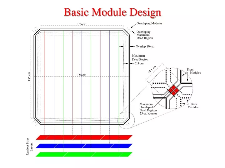
Basic Module Design. Module Layout. Modules are arrayed such that they only abut other modules at their corners. Mounting hardware, gas, high voltage and signal connectors are on the open edges.

E N D
Module Layout Modules are arrayed such that they only abut other modules at their corners. Mounting hardware, gas, high voltage and signal connectors are on the open edges. The full 7×7 array is completed with a complimentary second layer which overlaps the modules of the first layer.
Module Layout Modules are arrayed such that they only abut other modules at their corners. Mounting hardware, gas, high voltage and signal connectors are on the open edges. The full 7×7 array is completed with a complimentary second layer which overlaps the modules of the first layer.
System Efficiency The module efficiency is given by: where is the per plane efficiency and hits in m of n planes are required for a hit.
False Firing Rate and Dead Time The system random firing rate is given by: where R is the per plane rate (0.05 Hz/cm) A is the plane area (2.4 m2) and Δt is the coincidence time window (100 ns) The dead time due to tagging random firing is: Which results in tolerable dead times for all configurations, with reasonable assumptions.
The Numbers 7×7 modules on a side for 5 sides → 245 modules Assume 4 planes/module: 4 channels/plane → 3920 channels/detector 16 channels/plane → 15680 channels/detector With an electronics budget of $250K/detector 1 HV channel per module @ $200 each → $50K Leaving $50 (4 channel/plane) per channel or $12.50 (16 channel/plane) per channel