Download
1 / 11
110 likes | 212 Views
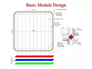
Alternate Module design. My major concerns with the 3D module design are cost and yield. We need to build ~200 m 2 of pixelated devices The modules in the long barrel design are large, 10x10 cm 2 The size unit for integrated circuits is about 2.5 x 2 cm.

E N D
Alternate Module design My major concerns with the 3D module design are cost and yield. • We need to build ~200 m2 of pixelated devices • The modules in the long barrel design are large, 10x10 cm2 • The size unit for integrated circuits is about 2.5 x 2 cm. • This means we need ~20 chips to populate a module • Oxide bonding of IC to sensor wafers is probably the most cost effective way to build such a large area system, but oxide bonding is not reworkable, so any bonding problem will affect the yield of a full module • This is the motivation for the active edge work • To really be cost effective we would like to bond 8” IC wafers to 8” sensor wafers
Active Edge • The standard active edge process requires etching a trench into the sensor wafer – needs to be established on 8” technology • A laser/wafer cleveing post-process which is being developed by UCSC/NRL could be considerably easier and less expensive – we are collaborating with them, keeping a section of the active edge wafers for tests of this technique.
Progress • Progress has been slow – dependent on the 3D IC industry • Tezzaron is still the only supplier of 3D Ics accessible to HEP • They depend on Global Foundries for 3DIC wafers • GF is not very sensitive to small customers - numerous screw-ups and miscommunications. MOSIS is not very happy • Tezzaron just acquired SVTC Austin • This was a SEMATECH R&D facility, bought by SVTC as a R&D center and about to go into bankrupcy • Tezzaron now has a strong fabrication facility and plans to develop a post-process via which can be used with a variety of IC vendor wafers. • We need to show significant progress in time for the TDR in 2014.
Alternate Design • The central feature of the long barrel design is the tracklet/track reconstruction, which enables very fast track finding. • This is linked to, but not dependent on our 3D interposer based design. It would be very useful to have a credible backup design which would fit in the long barrel geometry, utilize the rod design, and preserve the tracklet/track solution. • This would involve smaller modules • Utilize via-last 3D which is being explored at CERN • Essentially a variant of the CERN design which puts chips inboard.
Overview Readout bus Spacer Spacer Top Sensor Bottom Sensor Readout Chips Strip direction
Design features • The readout chips are via-last – TSVs are drilled in wafers after CMOS fabrication • almost any CMOS process can be used. • Chips must be thicker – 250 microns vsabout 20 • Top to bottom connections by flex cable. • Long strip connections to ROIC by wirebond rather than bump • Readout bus connections by wirebond – bus sits on IC • Long strips longer – 2.5 vs 1 cm. • Spacers must be thermally conductive –RVC foam • Twice as many modules – we will need to stagger them in radius to minimize dead area • This staggering can make the z=0 region easier to design.
Edge Region wirebond Top Sensor Flex Jumper Spacer wirebond 750m 250m Readout Chip TSV Bottom Sensor Bump bonds
10 cm Spacer 5 cm Readout Bus Spacer Readout Chip
Spacer Readout Bus Readout Chip
module RVC foam spacer 5 cm 4 cm