Download
1 / 50
630 likes | 1.55k Views
Equipment and Room Sizing. By Rob Moore 2017. Aim of Presentation. The aim of this presentation is to provide some guidance around the selection size and space requirements for HV (High Voltage) switchgear Transformers (TX) Main Switchboards (MSB) Distribution boards (DB)

E N D
Equipment and Room Sizing By Rob Moore 2017
Aim of Presentation • The aim of this presentation is to provide some guidance around the selection size and space requirements for • HV (High Voltage) switchgear • Transformers (TX) • Main Switchboards (MSB) • Distribution boards (DB) • Cable containment • UPS (Uninterruptable Power Supply) units • Battery strings • Generators
Topics • HV Switchgear • HV Switchgear rooms • Transformers • Transformer Rooms • Main Switchboards • Main Switchboard Rooms • Distribution Boards • UPS Units and Battery Strings • UPS Units and Battery Strings Rooms • Generators • Generator Rooms • Bulk Fuel Tanks
Space Planning • At the initial stages it is not really known what type and size of Switchgear, Transformer/s, Main switchboard, DB’s etc. will be provided however we will be required to provide an idea of space requirements
HV Switchgear • The requirement for HV switchgear is usually triggered when the project requires its own transformer on site. If the supply to the site is only at 400V then there may be no requirement for HV switchgear or transformer. • Generally the HV switchgear (11kV and 22kV) is provided and installed by the supply authority however there are occasions when the switchgear is owned and installed by the Client under the project. • When the switchgear is provided by the supply authority (Vector) for Auckland they are very specific around the types used and only use the following types at present as indicated in the latest ESE501 Vector Document (This document can be found in the Knowledge Centre) • ABB Safelink-2 SF6 for 11kV (Non-extendable) • ABB Safeplus SF6 for 22kV (Extendable) • Siemens 8DJH for 22kV (Extendable either side) It is strongly recommended that communication with the supply authority is undertaken in order to determine the type of switchgear which is to be installed at any particular location
HV Switchgear • Vector document ESE501 has provided some tables to assist with selection of switchgear as follows Extract from ESE501 Vector document
HV Switchgear Extracts from ESE501 Vector document
HV Switchgear • When the switchgear is to be provided under the project it is essential that the Client be consulted as to if there is a preference for the type of switchgear to be provided as these do vary in dimensions (size) depending on manufacturer. It is also important to establish the supply voltage as this will also have an impact on dimensions • For the initial planning the following should be used as a guide • Width=600mm • Depth=800mm • Height=1400mm • Access above=2600mm Single Switch unit Typical Ring Main Unit (RMU)
HV Switchgear rooms • The supply voltage to the project can be obtained from the supply authority from a simple phone call. • When deciding on the space that will be required, Vector have example layouts for HV switchgear locations and clearances. Refer to Vector drawings EDE 5015 to EDE 5019 (Copies in Knowledge Centre) • We recommend adopting these space requirements for rooms other than just for supply authority rooms. • Generally there is a requirement for a 3 or 4 way ring main unit (ie incomer switch, 1 or 2 transformer switches and outgoing switch) however in some instances Vector will require to install a 5 way ring main unit (ie incomer switch, 2 transformer switches and 2 outgoing switches) • If there is one transformer the HV switchgear can be located in the same room as a transformer. If there are two or more transformers then the HV switchgear will be required to be installed in a separate room
HV Switchgear rooms • For the initial space planning the following are the minimum clearances required for an HV switchgear room • Height 2800mm if trenches provided otherwise 3200mm • Clearance behind switchgear 200mm • Clearance in front of switchgear 2210mm • Clearance around switchgear 800mm (Remember to leave space for extension of switchgear) • Note that generally trenches are required to be provided in the switch room • Depth 900mm • Width 1000mm • The separate switch room if required, will require a man door 1000mm wide which opens to a safe area and opens in the direction of egress. Not into the adjacent transformer room
HV Switchgear rooms Trenches Extract from Vector EDE 5016 drawing HV Switchgear Extract from Vector EDE 5017 drawing Note that the dimensions indicated above will vary depending on equipment sizing
HV Switchgear rooms Extracts from Vector drawings series
Transformers • The initial load estimate will be based on a w/m2 basis and a number of lump loads. (How to estimate the load is covered in another presentation) • From this initial load estimate it can be determined as to the quantity and rating of transformer/s required. This will inform what size room will be required to accommodate the transformer/s • Below are some examples of some typical standard size transformers that will assist in space allocation for the transformer room
Transformers Dry Type Transformer Oil Filled Transformer This type of transformer is only common when it is Client supply. These have long lead times and are more expensive than the oil type This type of transformer is common when it is supply authority supply.
Transformers Standard transformer dimension as used by Vector Oil Filled Transformers Width Length Height
Transformers (Dry Type) Dimension without IP33 Enclosure This is information that is available from the transformer manufacturer. Dimensions will vary depending on manufacturer Dimension with IP33 Enclosure
Transformer Rooms • When deciding on the space that will be required Vector have example layouts for transformers locations and clearances. Refer to Vector drawings EDE 5011 to EDE 5018 (Can be located in Knowledge Centre) • We recommend adopting these space requirements for rooms for other than just supply authority rooms.
Transformer Rooms • For the initial space planning the following are the minimum clearances required for a transformer room • Height 2800mm (This may vary if trenches or if overhead cable ladder is provided) • Clearance behind transformers 600mm • Clearance in front of transformers 1000mm • Clearance between transformers 1000mm (If there are more than two transformers in a room then this dimension will change in order to remove a transformer without moving any other transformer • Note that generally trenches are required to be provided in the transformer room • Depth 900mm • Width 1000mm • The transformer room will require a double door 2000mm wide which opens to the exterior of the building and opens in the direction of egress. If the room houses Supply authority equipment they will require 24/7 access • It is important that you read and understand the supply authority requirements for transformer rooms. For Vector it is the EDE5011 document located in the Knowledge Centre
Transformer Rooms • In some instance a fuse frame will be required which also has an impact on transformer room layout and dimensions. • Below is a example from Vector for a room with a LV fuse frame HV switchgear Transformer Trenches LV Fuse Frame Note that the dimensions indicated above will vary depending on equipment sizing Extract from Vector EDE 5015 drawing
Transformer Rooms • Example of a room containing four transformers
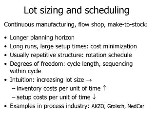
Main Switchboards • Based on the load to be supplied the rule of thumb for estimating a main switchboard size is • 1.5m per 200kVA for a high load main switchboard > 500kVA • 1.1m per 200kVA on a low load main switchboard <500kVA. • A more accurate estimate of size will be based on the number of outgoing ways, metering requirements, bus couplers and generator changeover switches and obtaining some guidance from a switchboard manufacturer. • There is a Design Guide currently being produced re Space planning for Main Switchboards and Rooms and this will be uploaded to Knowledge Centre when completed .
Main Switchboards • Example of typical Single Line Diagrams (Basic to complex)
Main Switchboards • Example of Main Switchboard
Main Switchboards • Below is a table indicating the size of main switchboards from some previous projects. • You will notice that the board size does vary depending on project type and the number of outgoing ways
Main Switchboard Rooms • The size of main switchboard rooms must comply with clearances etc. required as per AS/NZS3000. This needs to be highlighted to the Architect and no relaxation from this is to be given. If this is not provided you will end up with the verifier not signing the design off, a building that is non compliant, the electrical contractor not issuing a “Certificate of Compliance”, a very costly fix if at all possible and an inspector not permitting the installation to be livened • Items that need attention are as follows; • A switchboard room will require two means of egress spaced well apart if; • The board is longer than 3m OR • The board is rated at 800amps and above OR • The prospective short circuit of the board is 15kA or more • When sizing the room remember to make provision for all other items that are to be included in the room (ie. Power Factor Correction unit, any harmonic filters, control panels etc.)
Main Switchboard Rooms • For the initial space planning the following are the minimum clearances required for a main switchboard room • Height of room: 2800mm • Clearance behind switchboard (Depends on installation and configuration) • Clearance in front of switchboards: 1400mm • Typical depth of single sided board: 800mm • Typical depth of double sided board: 1600mm • Refer to Extracts from AS/NZS3000:2007 below
Main Switchboard Rooms • Extracts from AS/NZS 3000:2007
Main Switchboard Rooms Single Sided Main Switchboard
Main Switchboard Rooms Double Sided Main Switchboard
Distribution Boards (DB’s) • The sizing is typically carried out at preliminary design phase when more detail is available. • In order to determine the distribution board size one will need to know the quantity of circuits that will be supplied from the board • For lighting the following estimate can be done • From the areas known/determined one can estimate the light level required for each area. From basic calculations one can determine the quantity of luminaires required. Divide the number of luminaires calculated by the amount of luminaires one would connect to a circuit. Typically we would keep this number around 7 to 8 and you will get a rough idea as to the number of outgoing circuits for lighting that will be required. • For general power the following should be adopted; • Commercial offices: One circuit for every 20m2 • Hospitals: One circuit for every 15-20m2 • Schools: One circuit for every 30m2 • Universities: One circuit for every 10-20m2 depending on the type of facility
Distribution Boards (DB’s) • Other factors to take into consideration are as follows; • Metering requirements • HVAC items to be supplied from the DB in which case they will be from a separate section • Hot Water Cylinders • Exit signs • Control circuits • Requirements for double pole RCD’s (As per AS/NZS3000 or entire site) • Control Panel sections • Will the Client want a lighting section separate from a power section • Load shedding facilities (Contactors, relays etc.)
Distribution Boards (DB’s) • Typical examples of Distribution Board Layouts
Distribution Boards (DB’s) • For the initial space planning the following are the minimum clearances required for a distribution board location • If located within a DB cupboard: Full Height floor to floor • Clearance behind DB (Depends on installation and configuration) • Clearance in front of DB 1500mm • Typical depth of a DB is @ 300mm • Refer to Extract from AS/NZS3000 below
Cable Containment • There are various type of cable containment required to be used in an electrical installation. They range from • Cable Ducts • Cable Ladder • Cable tray • Cable trunking • Skirting duct • Conduits • Cable Basket There is a Design Guide in Knowledge Centre re Cable Support Systems Be aware of seismic support issues. This will be covered in another session
UPS Units and Battery Strings • At concept stage specific requirements are not known so questions need to be asked so that at Preliminary Design Stage areas for this can also be made available Further information on UPS units will be covered in another session
UPS Units and Battery Strings Battery Strings UPS Units
UPS Units and Battery Strings • Some typical items that require UPS backup are as follows; • Commercial Offices • Communication rooms data racks • Certain Work stations • Hospitals • Communication rooms data racks • Certain Work stations • Intensive Care Units • Schools • Communication rooms data racks • Universities • Communication rooms data racks • Certain Work stations • Certain items within a research laboratory • NOTE: This UPS cannot be used for emergency lighting. This will be covered in another presentation
UPS Units and Battery Strings Rooms • The following minimum clearances should be provided; • UPS Units • Room Height: 2800mm • In front of UPS: 1500mm • Sides of UPS: 800mm • Rear of UPS: 400mm • Between UPS Units: 1000mm • Battery Rack/Strings • Room Height: 2800mm • In front of Battery Rack: 1000mm • Sides of Battery Rack: 800mm • Rear of Battery Rack: 100mm • Between Battery Racks: 1000mm • Note • You also need to allow for distribution boards and by-pass switches
Battery Strings • Examples of UPS and Battery Room
Generators • At the initial stage little is known of the Clients requirements other than the requirement for a generator back-up and no actual design has been done. • Typically an architectural plan will be available which may or may not have areas indicated in m2 and then it is up to the engineer to determine these • The initial load estimate will be based on a w/m2 basis and a number of lump loads. (How to estimate the load is covered in another presentation) • From this initial load estimate the quantity and rating of generator/s can be determined. This will inform what size room will be required to accommodate the generator/s • In some instances the generators are located outdoors in an enclosure so space will need to be allocated for these installation types. Refer to images below in the next few slides to what this would look like
Generators • As generators by their nature run at a power factor of 0.8 a rule of thumb for selecting a generator from the electrical load estimate is as follows; • Below is typical example of information available from generator suppliers that will assist in space allocation for the generator room
Generator Rooms • Typical Clearance around a generator should be as follows; • Height of Room: • To the sides of the generator: Minimum of 800mm • Between generators: Minimum of 1000mm • To the rear of the generator: 1000mm to 1200mm • Items that are typically located within a generator room; • Day fuel tank • Fuel pipes • Generator control panel (Set mounted or wall mounted) • Distribution board • Mechanical ducting etc. • Attenuation in front of generator • Acoustic lining
Generator Rooms Example layout at concept
Generator Rooms Exhaust Primary Silencer Radiator Air Intake Filter Cooling Fan Turbo Engine (V16 65 litre) Control Panel Alternator Fuel Injection Starter Motor
Bulk Fuel Tanks • Determine the size/capacity of fuel tank required. • Refer to example calculation • Obtain standard size of fuel tanks from a supplier. Refer to next slide for example capacities etc • If the bulk fuel tank is to be located within the building the following clearances should be provided; • Height of Room: Minimum of 1200mm above top of tank • Clearance around tank: minimum of 800mm Note that there will also be space required for pumps etc. Discuss this with the Mechanical Engineer
Bulk Fuel Tanks Example capacities etc.
End of presentation • Hope this gives an overview of the basic principles to be adopted • Any Questions • Thank you for your time and remember if you are not sure about anything ASK your senior electrical engineer or any other senior electrical engineer for guidance