Download
1 / 16
180 likes | 208 Views
Multiplexers. Combinational logic circuit. Combinational Circuit Example. 8-line 2-to-1 Multiplexer. 8-line 2 x 1 MUX. a(7:0). y(7:0). b(7:0). sel y 0 a 1 b. sel. a(7:0). 8-line. 2 x 1. y(7:0). MUX. b(7:0). sel. An 8-line 2 x 1 MUX. library IEEE;

E N D
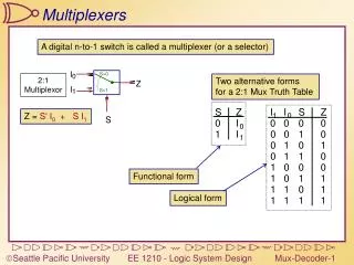
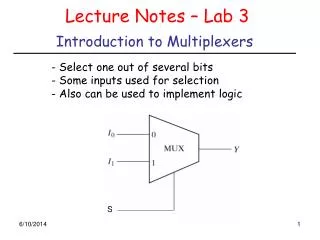
Multiplexers Combinational logic circuit
Combinational Circuit Example 8-line 2-to-1 Multiplexer 8-line 2 x 1 MUX a(7:0) y(7:0) b(7:0) sel y 0 a 1 b sel
a(7:0) 8-line 2 x 1 y(7:0) MUX b(7:0) sel An 8-line 2 x 1 MUX library IEEE; use IEEE.std_logic_1164.all; entity mux2 is port ( a: in STD_LOGIC_VECTOR(7 downto 0); b: in STD_LOGIC_VECTOR(7 downto 0); sel: in STD_LOGIC; y: out STD_LOGIC_VECTOR(7 downto 0) ); end mux2;
Entity Each entity must begin with these library and use statements library IEEE; use IEEE.std_logic_1164.all; entity mux2 is port ( a: in STD_LOGIC_VECTOR(7 downto 0); b: in STD_LOGIC_VECTOR(7 downto 0); sel: in STD_LOGIC; y: out STD_LOGIC_VECTOR(7 downto 0) ); end mux2; port statement defines inputs and outputs
Entity Mode: in or out library IEEE; use IEEE.std_logic_1164.all; entity mux2 is port ( a: in STD_LOGIC_VECTOR(7 downto 0); b: in STD_LOGIC_VECTOR(7 downto 0); sel: in STD_LOGIC; y: out STD_LOGIC_VECTOR(7 downto 0) ); end mux2; Data type: STD_LOGIC, STD_LOGIC_VECTOR(7 downto 0);
Standard Logic library IEEE; use IEEE.std_logic_1164.all; type std_ulogic is ( ‘U’, -- Uninitialized ‘X’ -- Forcing unknown ‘0’ -- Forcing zero ‘1’ -- Forcing one ‘Z’ -- High impedance ‘W’ -- Weak unknown ‘L’ -- Weak zero ‘H’ -- Weak one ‘-’); -- Don’t care
Standard Logic Type std_ulogic is unresolved. Resolved signals provide a mechanism for handling the problem of multiple output signals connected to one signal. subtype std_logic is resolved std_ulogic;
a(7:0) 8-line 2 x 1 y(7:0) MUX b(7:0) sel Architecture architecture mux2_arch of mux2 is begin mux2_1: process(a, b, sel) begin if sel = '0' then y <= a; else y <= b; endif; end process mux2_1; end mux2_arch; Note: <= is signal assignment
Architecture entity name process sensitivity list architecture mux2_arch of mux2 is begin mux2_1: process(a, b, sel) begin if sel = '0' then y <= a; else y <= b; endif; end process mux2_1; end mux2_arch; Sequential statements (if…then…else) must be in a process Note begin…end in process Note begin…end in architecture
Sel y “00” a “01” b “10” c “11” d An 8-line 4 x 1 multiplexer a(7:0) 8-line b(7:0) 4 x 1 y(7:0) c(7:0) MUX d(7:0) sel(1:0)
An 8-line 4 x 1 multiplexer library IEEE; use IEEE.std_logic_1164.all; entity mux4 is port ( a: in STD_LOGIC_VECTOR (7 downto 0); b: in STD_LOGIC_VECTOR (7 downto 0); c: in STD_LOGIC_VECTOR (7 downto 0); d: in STD_LOGIC_VECTOR (7 downto 0); sel: in STD_LOGIC_VECTOR (1 downto 0); y: out STD_LOGIC_VECTOR (7 downto 0) ); end mux4;
Sel y “00” a “01” b “10” c “11” d Example of case statement architecture mux4_arch of mux4 is begin process (sel, a, b, c, d) begin case sel is when "00" => y <= a; when "01" => y <= b; when "10" => y <= c; when others => y <= d; end case; end process; end mux4_arch; Note implies operator => Must include ALL posibilities in case statement
VHDL Architecture Structure architecture name_arch of name is begin end name_arch; Signal assignments Processes contain sequential statements, but execute concurrently within the architecture body Concurrent statements Process 1 Concurrent statements Process 2 Concurrent statements
Optional process label VHDL Process P1: process (<sensitivity list) <variable declarations> begin <sequential statements> end process P1; Within a process: Variables are assigned using := and are updated immediately. Signals are assigned using <= and are updated at the end of the process.