Download
1 / 38
390 likes | 639 Views
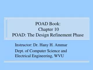
POAD Book: Chapter 9 POAD: The Design Phase. Instructor: Dr. Hany H. Ammar Dept. of Computer Science and Electrical Engineering, WVU. Outline. Review of the POAD Process The design phase consists of the following Constructing Pattern Level Diagrams

E N D
POAD Book:Chapter 9POAD: The Design Phase Instructor: Dr. Hany H. Ammar Dept. of Computer Science and Electrical Engineering, WVU
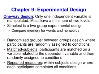
Outline • Review of the POAD Process • The design phase consists of the following • Constructing Pattern Level Diagrams • Constructing Pattern-Level with Interfaces • Constructing Detailed Pattern Level • Deliverables • High level view of the application • Pattern-Level with Interfaces Diagram • Detailed Pattern Level Diagram
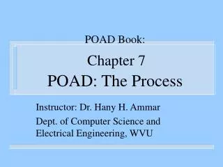
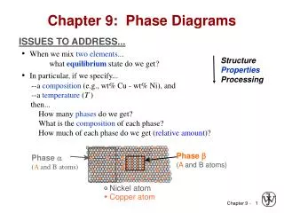
Application Requirements Requirement Analysis Required Conceptual Components Acquaintance Pattern Library Retrieval Selection Analysis Candidate Patterns Selected Patterns Design Design Refinement Create Pattern Instances Selected Patterns Define Pattern Relationships Constructing Pattern-Level models Construct Pattern-Level Diagrams Pattern-Level Diagrams Declare Pattern Interfaces Constructing models for Pattern-Level with Interfaces Identify Relationships between Pattern Interfaces Pattern-Level with Interfaces Diagrams Constructing models for Detailed Pattern-Level Detailed Pattern-Level Diagrams (c) Design The POAD process a) overall phases, b) analysis, c) design, and d) design refinement (b) Analysis (a)Overall POAD Detailed Pattern-Level Diagrams (d) Design Refinement Concretization Instantiating Pattern Internals Specialization Domain Specific Detailed Pattern-Level Diagrams Develop Class Diagrams Initial UML class diagram Reduction Design Optimization Merging & Grouping Optimized class diagram
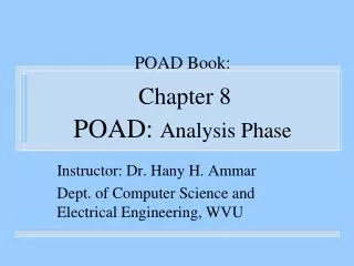
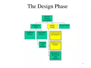
The Selected Patterns & Analysis Documentation Create Pattern Instances Constructing Pattern-Level models Define Instance Relationships Construct Pattern-Level Diagrams Pattern-Level Diagrams Declare Pattern Interfaces Constructing the Pattern-Level with Interfaces models Identify Interface Relationships Pattern-Level with Interfaces Diagrams Constructing the Detailed Pattern-Level models Detailed Pattern-Level Diagrams Overall Design Phase
Constructing Pattern Level Models • Purpose – To create Pattern Level Models for the application. • Process • Creating Pattern Instances • Designer creates Instance for each pattern selected • Two steps to Instantiation • Identify Name and type of Pattern • Giving application Specific names to Pattern Internals (deferred to the design refinement phase) • Consider a sensor controlled by an application (from feedback example)
Error (Actuating) Signal Controlled Output Feed forward Elements Reference Input + + Feedback Data Feedback Elements Measurement Plant. Constructing Pattern Level Models
Constructing Pattern Level Models • For this application the analyst uses observer pattern • The application Specific name can be FeedbackObserver. • application design contains pattern instance called FeedbackObserver of type Observer • Multiple Instances of Same type • instance name distinguishes which pattern is referred • In the feedback example another observer is used to monitor the error between inputs and feedback data • i.e. ErrorObserver
Constructing Pattern Level Models • Defining Pattern Instance Relationships • In POAD pattern relationships are dependencies • Designer Studies existence of relationships and direction. • E.g the designer has decided to use ForwardStrategy to control the mechanisms of the plant. • Output from ErrorObserver triggers the ForwardStrategy instance • Hence designer creates dependency relationship from the ErrorObserver to the ForwardStrategy
<<Observer>> FeedbackObserver <<Strategy>> <<Observer>> Apply forward control strategy FeedforwardStrategy ErrorObserver Constructing Pattern Level Models • Develop Pattern Level Diagrams • UML models used to represent Pattern-Level diagrams
Constructing Pattern Level Models • Subsystems and Frameworks • For large applications it is wise to divide the application into a set of subsystems • designer will construct a Pattern-Level diagram for each individual subsystem • Product - Pattern-Leveldiagrams for the application and for each individual subsystem or framework.
Design Tips • The designer should use the analysis results including the definition of design components and how the selected patterns are anticipated • Study the dynamics: Attempting to study the application dynamics will help the analyst identify the dependency relationships between pattern instances • Meaningful names: When choosing application specific names for the pattern instance, the designer should choose names that are meaningful in the application context. When there are • Revisit the analysis phase: the designer might find that the patterns selected by the analyst are not suitable
Plant <<Observer>> <<Strategy>> FeedbackObserver FeedforwardStrategy Apply feedback control strategy Apply forward control strategy <<Strategy>> <<Observer>> FeedbackStrategy ErrorObserver Calculate Error Manipluate Data Manipulate Data Manipluate Data <<Blackboard>> Blackboard Examples Pattern Level Diagram: Feedback control system
Example 2: The Simulation of Waiting Queues (POAD: Ch. 12) • Conceptual Components • Customer generator.The customer generator component uses one of a distribution function to generate the time of arrival • Queue facility.The queue facility component consists of a set of queue categories, where each queue category contains one or more queues • Service facility. The service facility component consists of a set of service categories, where each service category contains one or more servers. • Event manager.The event manager component serves as the main driver for the simulation and produces simulation measurements (results).
The Simulation of Waiting Queues (POAD: Ch. 12) • Pattern Selection (cont.) • Customer Generator component use a distribution function to generate the next customer to arrive • Select the TemplateMethod pattern as an interface for generating customers (TemplateMethod pattern defines the skeleton of an algorithm (in our case study the steps required to generate a customer) • The Event Manager (Scheduler) component plays the role of demultiplexing and dispatching of events • select the Reactor pattern to implement the design of the Event Manager (supports the “de-multiplexing and dispatching of events to multiple event handlers triggered concurrently by multiple events, • The Queuing and Service facilities components • Select the Composite Pattern to support composite queues/servers
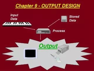
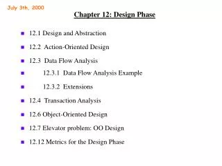
Example 3:A Digital Content Remastering Application (POAD Ch.13)
A Digital Content Remastering (DCRM) Application (POAD Ch.13) • Requirements: DCRM consists of several subsystems • The Distributionsubsystem, a subsystem that deals with the distribution of tasks across the worker machines • The Filtering Subsystem, a subsystem that handles the application of several content-understanding algorithms • The controller engine subsystem that handles the workflow logic and masters the execution of components in the system.
A Digital Content Remastering (DCRM) Application (POAD Ch.13) • The Distributionsubsystem Requirements • Provide the necessary communication mechanisms to communicate with all worker machines • Be extensible to support several communication technologies, and be able to communicate with heterogeneous worker machines • Provide a mechanism for distributing tasks to worker machines, and be extensible in terms of the number of machines it supports,
A Digital Content Remastering (DCRM) Application (POAD Ch.13) • Conceptual Components • Task Distribution Component • Communication Component • Acquaintance, Retrieval, Pattern Selection • the literature is full of patterns for distributed and communication systems • Some candidates include the Proxy pattern and the Strategy pattern, and the Abstract Factory pattern
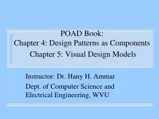
A Digital Content Remastering (DCRM) Application (POAD Ch.13)
The Selected Patterns & Analysis Documentation Create Pattern Instances Constructing Pattern-Level models Define Instance Relationships Construct Pattern-Level Diagrams Pattern-Level Diagrams Declare Pattern Interfaces Constructing the Pattern-Level with Interfaces models Identify Interface Relationships Pattern-Level with Interfaces Diagrams Constructing the Detailed Pattern-Level models Detailed Pattern-Level Diagrams Overall Design Phase
Constructing Pattern Level with Interfaces • Purpose - analyze the relationships between instances and define relationships between interfaces • Process • Exposing the Instance Interfaces • Recall Interfaces can be interface operations or interface classes. • During this phase the designer determines the interfaces used to hook the patterns • Interface definition is buried deep in pattern documentation and is not explicitly defined
Constructing Pattern Level with Interfaces • Patterns can have Multiple Interfaces • Identifying the relationship between Pattern Instance Interface • Designer decides which interface to use, and constructs the relationship between pattern interfaces and instances. • The UML relationship “realizes” indicates a pattern implements a specific interface.
<<Strategy>> FeedforwardStrategy Context <<Observer>> ErrorObserver Notify Update Constructing Pattern Level with Interfaces • Revisit Slide 7 where the ErrorObserver uses the ForwardStrategy Instance. • Observer has 2 interface operations, update() and notify()
Constructing Pattern Level with Interfaces • ForwardStrategy instance has interface class context() • as the input values change the control strategy should be applied to control the plant. • Thus the update() operation invokes the context interface • Update interface will be connected to the Context interface using a dependency relationship
Constructing Pattern Level with Interfaces • Interface Relationships • We could have 2 types of interfaces, class or operation • Thus we have 4 possible dependencies between patterns • Class-class, class-operation, operation-class, operation-operation. • These dependencies will be further investigated in the next step of the design phase when constructing a detailed pattern-level model
Constructing Pattern Level with Interfaces • Product- Constructing the pattern level with interfaces model.
<<Strategy>> FeedforwardStrategy (from POAD1-Feedback) Pattern Level with interfaces diagram for feedback control system <<Observer>> Notify FeedbackObserver (from POAD1-Feedback) Context Update <<Strategy>> Notify <<Observer>> FeedbackStrategy ErrorObserver (from POAD1-Feedback) (from POAD1-Feedback) Context Update getData <<Blackboard>> Blackboard (from POAD1- Feedback) setData
The Selected Patterns & Analysis Documentation Create Pattern Instances Constructing Pattern-Level models Define Instance Relationships Construct Pattern-Level Diagrams Pattern-Level Diagrams Declare Pattern Interfaces Constructing the Pattern-Level with Interfaces models Identify Interface Relationships Pattern-Level with Interfaces Diagrams Constructing the Detailed Pattern-Level models Detailed Pattern-Level Diagrams Overall Design Phase
Constructing Detailed Pattern-Level Models • Purpose- To reveal the internal design structure of the pattern instances used in the Pattern-Level with Interface diagrams . • Process- Explore the pattern structure • POAD is structure based composition approach. • Class diagram for each pattern is expected to be a part of a pattern database. • Designer studies study internal class diagram of patterns used in Pattern-Level with Interfaces diagram
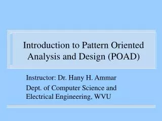
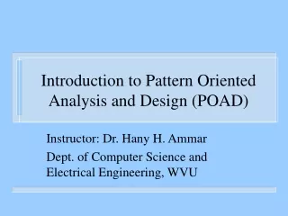
Constructing Detailed Pattern-Level Models • The following figure shows the Detailed Pattern Level diagram for the previously discussed example. It shows the internals of each pattern • The designer studies participants in the class diagram and the roles they play in solving the design problem
<<Strategy>> FeedforwardStrategy Strategy Context AlgorithmInterface() ContextInterface() Context ConcreteStrategyB ConcreteStrategyA AlgorithmInterface() AlgorithmInterface() <<Observer>> InputObserver Subject Observer Attach() Detach() n n Update() Notify() ConcreteSubject ConcreteObserver Update subjectState Notify observerState getState() Update()
Constructing Detailed Pattern-Level Models • Dynamic Aspects- explain how pattern participants communicate with each other. • Realization of the Interface- identify which elements of the pattern internals are exposed as interfaces. • Trace interfaces to pattern internals • Product- Detailed Pattern Level Diagram
<<Strategy>> <<Observer>> FeedforwardStrategy FeedbackObserver (from POAD1-Feedback) (from POAD1-Feedback) Subject Context Strategy Observer Attach() ContextInterface() AlgorithmInterface() n n Update() Detach() Notify() Notify Context ConcreteStrate ConcreteStrate ConcreteOb ConcreteS gyA gyB server ubject observerState subjectState AlgorithmInterface() AlgorithmInterface() Update() getState() <<Observer>> ErrorObserver (from POAD1-Feedback) Update <<Strategy>> FeedbackStrategy Subject (from POAD1-Feedback) Observer Attach() n n Update() Detach() Notify() Context Strategy Update Notify ContextInterface() AlgorithmInterface() Context ConcreteObserver ConcreteSubject observerState subjectState Update() getState() ConcreteStrategyB ConcreteStrategyA AlgorithmInterface() AlgorithmInterface() setData getData <<Blackboard>> Blackboard (from POAD1-Feedback) Blackboard DataHolder setData() getData() n n ConcreteDataHolderA ConcreteDataHolderB Detailed pattern Level Diagram Feedback control system