Download
1 / 2
30 likes | 154 Views
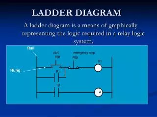
I-1,3. I-0,0. O-0,1. To FCE motor. Start P.B. TSH. Input Modules. Output Modules. Motor. O-0,1. Starter. WBT-4. 24 volts. 120 volts. 120 volts. 48 volts. 120 volts. 24 volts. (active low). I-0,3. I-1,3. O-0,3. O-1,3. TSH. “We-build-them”. N.O. Programmable Controllers.

E N D
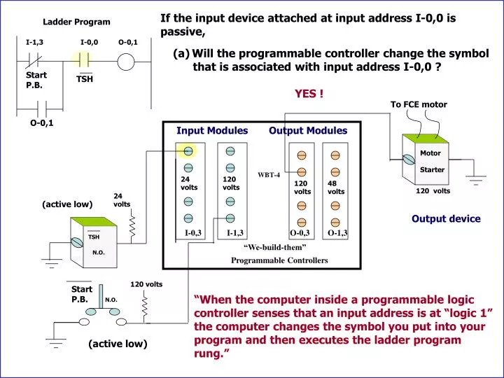
I-1,3 I-0,0 O-0,1 To FCE motor Start P.B. TSH Input Modules Output Modules Motor O-0,1 Starter WBT-4 24 volts 120 volts 120 volts 48 volts 120 volts 24 volts (active low) I-0,3 I-1,3 O-0,3 O-1,3 TSH “We-build-them” N.O. Programmable Controllers Start P.B. If the input device attached at input address I-0,0 is passive, Ladder Program • Will the programmable controller change the symbol • that is associated with input address I-0,0 ? YES ! Output device 120 volts “When the computer inside a programmable logic controller senses that an input address is at “logic 1” the computer changes the symbol you put into your program and then executes the ladder program rung.” N.O. (active low)
Safety Alarm #1 Safety Alarm #2 Y alarm X FCE y –(x+1) FCE y –(x+1) LED LED LED LED C S DSP y- x 1 1 1 1 - - - - 1 2 2 0 X Y S S S S C C C C 2 1 0 3 2 1 3 0 U7 X B A 0 D 0 0 0 A A A A A A A A X A B FCE y-(x+1) 1 1 D 7 6 5 4 3 2 1 0 1 1 LED X A B D 2 0 - 2 2 2 - Wr/Rd 2 2 2 B X U6 Enable 3 3 A D 3 3 A = B ToCk on U1 To Ck on U1 U-Betch_UM The active signal from U7 reports to the Ck input of U1. Best Process Process Final Control Element Operation Selection The pulse on the Ck input of U1 increase the count value on the Q outputs by 1 value. Version 1-2 LED LED 2 - 1 LED Sequence - 3 2 reset P.B. The change in the Q outputs selects a new channel on the decoder and a new address is delivered to U6. CL C U2a Q 1Y0 0 1A Load A C 1Y1 Q 1 1B B A 1Y2 74139 C 2 U1 Carry B 1Y3 1E C 3 C 0volts D The new address on U6 selects a new memory location and the content of that memory location appears on the D outputs. S Q 2Y0 0 U2b 2A C S 2Y1 From U7 1 2B Q Ck D A=B 2Y2 S 74139 74161 2 2E 2E S S 0volts 2Y3 3