Download
1 / 33
330 likes | 442 Views
LHC Injectors Upgrade Project Overview. R. Garoby for the LIU Project Team. OMCM workshop - 22/06/2011. Introduction Planned actions Status of investigations Estimated beam characteristics Planning Summary. Objectives § Organization. Mandate

E N D
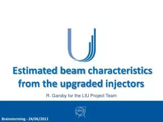
LHC Injectors Upgrade Project Overview R. Garoby for the LIU Project Team OMCM workshop - 22/06/2011
Introduction • Planned actions • Status of investigations • Estimatedbeamcharacteristics • Planning • Summary
Objectives § Organization • Mandate “The LHC Injectors Upgrade should plan for delivering reliably to the LHC the beams required for reaching the goals of the HL-LHC. This includes LINAC4, the PS booster, the PS, the SPS, as well as the heavy ion chain.”
320 ns beam gap PS ejection: 72 bunches 72 bunches on h=84 in 1 turn Quadruple splitting at 25 GeV Acceleration 18 bunches to 25 GeV on h=21 Triple splitting at 1.4 GeV PS injection: 6 bunches 3+3 bunches on h=7 in 2 batches bucket Empty Generation of LHC beam in the PS complex Division by 2 of the intensity in the PSB (one bunch per ring and double batch filling of the PS) Increase of the injection energy in the PS (from 1 to 1.4 GeV) Quasi-adiabatically splitting of each bunch 12 times in the PS to generate a train of bunches spaced by 25 ns Compression of bunches to ~4ns length for bunch to bucket transfer to the SPS Stacking of 3-4 PS batches in the SPS and acceleration to 450 GeV 40 MHz RF 1.1 × 10¹¹ ppb & 20 MHz RF 2.2 ´ 1011 ppb 10 MHz system RF = 9.18 MHz 4.4 ´ 1011 ppb 40 MHz + 80 MHz RF 10 MHz system RF = 3.06 MHz 13.2 ´ 1011 ppb
Introduction • Planned actions • Status of investigations • Estimatedbeamcharacteristics • Planning • Summary
Principles of action • To increase performance • Brightnessä • Increase injection energy in the PSB from 50 to 160 MeV, Linac4 (160 MeV H-) to replace Linac2 (50 MeV H+) • Increase injection energy in the PS from 1.4 to 2 GeV, increasing the field in the PSB magnets, replacing power supply and changing transfer equipment • Upgrade the PSB , PS and SPS to make them capable to accelerate and manipulate a higher brightness beam (feedbacks, cures against electron clouds, hardware modifications to reduce impedance…) • To increase reliability and lifetime (until ~2030!) • (tightlylinkedwithconsolidation) • Upgrade/replace ageing equipment (power supplies, magnets, RF…) • Procure spares • Improve radioprotection measures (shielding, ventilation…)
Linac4: Commissioning schedule M. Vretenar Start of beam commissioning (3MeV): May 2013 End of beam commissioning (160 MeV): April 2014 (version November 2010) 3 MeV 10 MeV 50 MeV 100 MeV 160 MeV 5 commissioning stages: In 2013/14 (15 months), 6.5 months of beam commissioning, 3 months of HW tests, 5.5 months of installation
Upgrade Work Packages + Consolidation…
PS injector – RCS option Tentative RCS parameters => Same beam characteristics than PSB @ 2GeV => Shorter PS § SPS injection flat bottoms K. Hanke • Benefits: • Competitivecostwrt PSB consolidation and upgrade (? Study in progress…) • Reliability (new hardware / modern design) • Commissioningdecoupledfromphysicsoperation
Introduction • Planned actions • Status of investigations • Estimatedbeamcharacteristics • Planning • Summary
PS injector: RCS feasibilitystudy • Beamcharacteristics: • for all PS users: equivalent to PSB at 2 GeV • for ISOLDE: ~ 7 1013 p/s @ 2 GeV (today: ~1013 p/s @ 1.4 GeV) • Feasibility report with • costestimate:end of July
PS Longitudinal: Batch Compression (1/2) MD tests – H. Damerau, S. Hancock – May 2011
PS Longitudinal: Batch Compression (2/2) Simulation (C. Carli) MD resultat 2 GeV (H. Damerau, S. Hancock) Pure h = 21 Pure h = 9 • RF gymnastics OK up to intermediate energy • Significant effort required to reach 26 GeV and make beam available for the SPS (RF preparation § beam adjustment) => Need for precise measurement of transverse emittances before continuing
Transverse: Principle of Tune Scans E. Benedetto • GOAL: Identify dangerous resonance lines in tune diagram • Loss measurement for different WPs: • Low intensity beam (not SC-dominated) → 130 x 1010 protons • Large emittance (to fill the chamber & provoke immediate losses) • Long flat bottom @ 1.4 GeV • Tune program: • Scan between (0.1 - 0.4) • Vertical tune constant • Sweep of the horizontal tune • Slope in the intensity signal indicates importance of the crossed resonance line
Transverse: PS Tune Scans E. Benedetto • 2 GeV • w/o PFW :no surprises • with PFW ongoing
Transverse: SPS Tune Scans H. Bartosik • Identified resonances in the low gt optics • normal sextupole resonance Qx+2Qy is the strongest • skew sextupole resonance 2Qx+Qy quite strong !!?? • normal sextupole Qx-2Qy, skew sextupole resonance at 3Qy and 2Qx+2Qy fourth order resonances visible • Identified resonances in the nominal optics • normal sextupole resonance Qx+2Qy is the strongest • Coupling resonance (diagonal, either Qx-Qy or some higher order of this), Qx-2Qy normal sextupole • skew sextupole resonance 2Qx+Qy weak compared to Q20 case • It seems that the stop-band width of the vertical integer is stronger than in Q20 optics
Transverse emittance measurement: debugging… A. Guerrero § B. Mikulec • Emittance preservation (?) between • PS @ 26 GeV and SPS flat bottom Emittance Blow-up (?) between PSB and SPS flat bottom
Transverse: emittances vs intensity in SPS H. Bartosik • Measurement of single bunch emittances • In scan with “reference” wire scanner BWS.519 at flat top • Long cycle (~10s injection plateau, ~10s acceleration) • Losses along the cycle extracted from DC-BCT measurement • PS bunch length increasing with intensity • Τ=2.9ns @ 1.5e11 p/b, Τ=3.5ns @ 3e11 p/b • Emittances in PSB: ~ 1μm < 1.5e11p / ~ 1.1μm @ 2e11p / ~ 1.3μm @ 3e11p (Well adjusted beam in the PSB!)
SPS: e-cloudwith 25 ns bunch train M. Taborelli • Electron cloud measured at all the liners • Signal already visible with 1 batch on both stainless liners • No signal visible on the a-C coating liner • Half signal clearly visible on the half coated chamber • Effect of the clearing electrode checked scanning points on a grid of voltage vs. magnetic field values Clearing electrode: it was switched off in the middle of cycle Half-coated liner, only stripe on StSt visible
Introduction • Planned actions • Status of investigations • Estimatedbeamcharacteristics • Planning • Summary
Caveat… • Beamparameters are givenat injection in LHC: beamloss and blow-up inside the LHC are not accounted for. • All necessaryimprovements are implemented in the injectors (Linac4, PSB to PS transferat 2 GeV, coupledbunchinstabilitiessuppressed, e-cloudsuppressed, hardware upgraded…) • Estimatedbeamdegradationin the acceleratorchain (basedon observations in 2010): • PS: 5 % beamloss, 5 % transverse blow-up • SPS: 10 % beamloss, 5 % transverse blow-up. • RF gymnasticsbeingkept, imperfections are unchanged: • +-10 % fluctuation of all bunchparameterswithin a given PS bunch train. • Traces of ghost/satellite bunches.
Beamparametersat LHC injection [50 ns] Nominal performance Baseline (estimatedlimit of SPS) Stretched: (estimatedlimit of SPS injectors) Q2/2011 Beam Parameters at 7 TeV MD: double PSB batch H/V transverse emittances [mm.mrad] MD: single bunchwithlowgt ? ? Bunchintensitywithin constant longitudinal emittance [x1011 p/b]
Beamparametersat LHC injection [25 ns] Nominal performance Baseline (estimatedlimit of SPS) Stretched: (estimatedlimit of SPS injectors) MD: double PSB batch Beam Parameters at 7 TeV H/V transverse emittances [mm.mrad] MD: single bunchwithlowgt ? ? Bunchintensitywithin constant longitudinal emittance [x1011 p/b]
Planned actions • Status of investigations • Estimatedbeamcharacteristics • Planning • Summary
Planned actions • Status of investigations • Estimatedbeamcharacteristics • Planning • Summary
Summary • MDs during 2011-2012 are essential to refine the knowledge and understanding of the injectors and to check the potential of upgrades. • Preliminary requirement/First goal: getting confidence in beam instrumentation => Extensive debugging: progressing well, but time –consuming... • Recent observations in 2011 tend to demonstrate that the accelerators perform better than in the previous years. Not fully understood. • Need for close interaction with HL-LHC for selecting reachable beam parameters. • Irrelevant to the decision to connect Linac4 to the PSB during LS1 and to the choice between PSB/RCS, the beam characteristics specified for LIU will be met some time after the end of LS2 (~2020).
THANK YOU FOR YOUR ATTENTION!
Whyistoday’sbeambetterthan nominal? • Simple! No more blow-up along the accelerators cascade… • PSB: • Improved (achromatic) optics in the Linac2 to PSB transfer line since 2005 [http://khanke.home.cern.ch/khanke/papers/2006/ab_note_2006_001.pdf] • PS: • Injection trajectories • Working point along the whole cycle • Transition • PS to SPS: • Transverse matching with better optics in TT2-TT10 WARNING: NO MARGIN LEFT!
Beamparameters: Comments Baseline (estimatedlimit of SPS) Constant longitudinal density (Longitudinal instabilities) + Constant total beamcurrent (RF power) Beam Parameters at 7 TeV H/V transverse emittances [mm.mrad] Constant transverse density (Space charge) Stretched (estimatedlimit of SPS injectors) Bunchintensitywithin constant longitudinal emittance [x1011 p/b]
Beamparametersat LHC injection [50 ns] Nominal performance Baseline (estimatedlimit of SPS) Stretched: (estimatedlimit of SPS injectors) Beam Parameters at 7 TeV H/V transverse emittances [mm.mrad] < ½ longit. emittance wrt 25 ns duringacceleration in the PS => Less Landau damping + e-cloudseffects ? ? ? Bunchintensitywithin constant longitudinal emittance [x1011 p/b]
Beamparametersat LHC injection [25 ns] Nominal performance Baseline (estimatedlimit of SPS) Stretched: (estimatedlimit of SPS injectors) Beam Parameters at 7 TeV H/V transverse emittances [mm.mrad] ? ? Bunchintensitywithin constant longitudinal emittance [x1011 p/b]