Download
1 / 28
280 likes | 598 Views
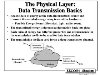
The Physical Layer: Data Transmission Basics. Encode data as energy at the data (information) source and transmit the encoded energy using transmitter hardware: Possible Energy Forms: Electrical, light, radio, sound. The transmitted energy is decoded at destination back into data.

E N D
The Physical Layer: Data Transmission Basics • Encode data as energy at the data (information) source and transmit the encoded energy using transmitter hardware: • Possible Energy Forms: Electrical, light, radio, sound. • The transmitted energy is decoded at destination back into data. • Each form of energy has different properties and requirements for the transmission media to be used for data transmission. • The transmission medium used forms a data transmission channel. Transmission Channel
Data Transmission Channel Characteristics • Channel Noise: A small amount of background interference or stray energy present on the channel (usually electro-magnetic)that carries no data or information. • Main cause of transmission errors. • Given as the signal to noise ratio S/N and measured in decibels (dB). • Channel Bandwidth: The size of the range of frequencies that can be transmitted through a channel. Measured in Hertz (Hz). Affected by: • Type and physical characteristics of media used. • Amount of noise present in transmission channel • Data encoding method used. • Channel Data Transmission Rate (or Bit Rate): The maximum number of bits that can be transmitted per unit time through the physical medium. Measured in bits per second (bps). • Channel Utilization: The fraction of the channel’s data rate actually used to transmit data.
Data Transmission Channel Characteristics • Channel Latency, or Propagation Delay: The amount of time needed for information to propagate from source to destination through the channel. It is the distance divided by the signal propagation speed (usually the speed of light). Depends on: • Media characteristics • Signal propagation speed • Transmission distance • Transmission Delay: The time it takes to transmit a message through the channel. It is the size of the message in bits divided by the data rate (in bps) of the channel over which the transmission takes place. • Bit Length: The length of a one-bit signal being transmitted = signal propagation speed / data transmission rate Example: Channel data-rate is 10Mbps. One bit is transmitted in 10-7 seconds. Since signals propagate in a medium at about 200,000 km/s, ie 2*108 m/s, bit-length is: 10-7 * 2 * 108 = 20 meters.
Transmission Media • Magnetic media: • e.g. disk, 8-mm tape bandwidth = 56 648 Mbps. • Twisted pair: Two insulated copper wires. • Baseband coaxial cable: • Possible bandwidth = 1 to 2 Gbps for 1 km cable. • Broadband coaxial cable: • Uses analog transmission up to 100 km • Bandwidth = 300-450 MHz • Fiber Optics: • Single mode fiber optics: bandwidth several Gbps over 30km • LEDs and semiconductor lasers are used as signal sources.
Copper Twisted Pair and Coaxial Cable Mature technology, rugged and inexpensive; Maximum transmission speed is limited: Low noise immunity Relatively short maximum transmission distances. Suitable for LANs. Twisted pair plastic-coated copper wires Coaxial cable cross-section
Fiber Optics Networks Compared to copper wiring: Higher speed ( > 1Gbps), more resistant to electro-magnetic interference, spans longer distances making it suitable for subnet channels, more expensive; less rugged. Requires only a single fiber.
The Physical Layer: Basic Information Encoding Theory • Any well behaved periodic function g(t) with a period T= 1/f can be decomposed into a summation of a series of sine and cosine terms (Fourier Series): • Any physical transmission channel can transmit frequencies undiminished from 0 to some frequency fc • e.g. voice grade phone lines have a cutoff frequency of fc= 3000hz • Channel baud rate = number of changes/sec • Channel bit rate = (baud rate x number of bits/change) bits/sec
The Maximum Data Rate of A Channel: Nyquist’s Theorem • The maximum data rate of a finite bandwidth noiseless transmission channel with bandwidth H is given by Nyquist’s theorem : Maximum data rate = 2 H log2 V bits/sec where V is the number of discrete levels. • For binary transmission: Maximum data rate = 2 H log 2 2 = 2 H • Given a channel with bandwidth H Hz, a signal S to noise N ratio of (10 log10 S/N) dB(decibels) , the maximum data rate of the channel (or channel bandwidth) is given by Shannon as: Maximum number of bits/sec = H log2 (1 + S/N) • e.g. phone lines have S/N ratio of 30 dB and H = 3000, according to Shannon: 30 dB = 10 log10 S/N Signal to noise ratio = S/N = 10 30/10 = 103 = 1000 Maximum transmission rate = 3000 log2 (1 + 1000) » 30000 bps
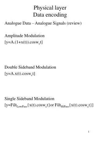
Data Encoding: Modulation • Why? Sine waves propagate better than square waves. • In a bandwidth limited channel (such as a phone line), the higher frequencies or harmonics of a square wave cannot be transmitted resulting in severe signal distortion. • To avoid this problem, the data is send only as sine waves. The data is transmitted by modulating the sine wave with a modulator-demodulator (modem). • Different modulation techniques include: • Amplitude Modulation: The amplitude of the sine wave is changed. • Frequency Modulation: The frequency of the sine wave is changed. • Phase Shift Modulation: The phase of the sine wave is changed.
Data Encoding: Binary Signal Modulation • Used to overcome: • Loss of signal energy • (attenuation). • Delay distortion • Noise. Binary Signal Amplitude modulation Frequency modulation Phase Modulation
Modulated Data Transmission Over Phone Lines • Digital signals are modulated at the sender and demodulated • at the receiver using modems. • Digital communication between computers/modems is handled using serial communication and the RS-232C interface.
The RS-232-C Serial Interface • Industry standard for serial data communication • Used to transmit character data (e.g. connect keyboard to computer or modem to computer). • -15 volts is used to represent 1 and +15 volts to represent 0. When the line is idle the voltage is kept at -15 volts. • Each character is transmitted asynchronously (i.e. the time interval between successive characters can be of any length) but within a character bits are transmitted synchronously (i.e. at fixed time intervals). • Maximum data rate = 115 kbps max. distance = 50 ft • The transmission starts with a start bit (a 0) and ends with a stop bit. In between are sent 7 bits that encode the character.
The RS-232-C Serial Interface • A simple example of physical layer protocols. • Character transmission based on an action-reaction (Hand-Shaking) • operation protocol.
The Digital Phone/Cable Network Digital signal Copper TV cable or phone twisted pair Analog signal: The local loop
Data Multiplexing • Transmission links (channels) present in a single network usually have a wide range of available bandwidths. • To maximize the utilization of higher bandwidth links: • Data from several lower-bandwidth transmission links is usually multiplexed onto a single high-bandwidth link. • Several data multiplexing methods are used: • Frequency Division Multiplexing (FDM) • Used in voice channels • Uses analog circuits • Wavelength Division Multiplexing (WDM): • Used in fiber optic transmission lines. • Time Division Multiplexing (TDM): • Several digital channels are combined from local subnets.
Frequency Division Multiplexing (FDM) • Used over copper or microwave channels • Uses analog signals and circuits not digitally. • Generally used to multiplex 12 voice channels onto a single 60-108 kHz line. • Each channel uses 4000Hz: 3000Hz for information, 500Hz on each side as guard
Wavelength Division Multiplexing (WDM) • A variation of Frequency Division Multiplexing used in fiber optics. • Different frequency Signals from several fiber optics are combined optically. • Possible single-fiber bandwidth: 25000 GHz • Current electrical to optical signal conversion is limited to the of 1-4 GHz range.
Time Division Multiplexing (TDM) • Digital data from a number of low-bandwidth channels is combined into a single high-bandwidth channel. • Data from different channels is multiplexed over time to occupy alternating time slots. • Example: T1 digital channels (1.554 Mbps) usually combine data from 24, 56000 bps channels.
Multiplexing T1 Onto Higher Channels Time division multiplexing is used to combine multiple T1, T2 etc. lines onto single higher-bandwidth lines.
Digital Optical Transmission Standards • SONET (Synchronous Optical NETwork) • SDH (Synchronous Digital Hierarchy) Data Multiplexing in SONET
Circuit Vs. Packet Switching Circuit switching Message switching Packet switching
Virtual Circuits • When a virtual circuit is established: • The route is chosen from beginning to end (circuit setup needed). • Routers or switches along the circuit create table entries used to route data transmitted on the virtual circuit. • Permanent virtual circuits. - Switched virtual circuits.
Asynchronous Transfer Mode (ATM) • Unlike SONET and SDH, uses asynchronous transmission. • Cell-based packet-switched transmission. • Cells may be encased in a carrier (T1, T3, SONET). • No requirement that cells must alternate between sources. • Virtual circuit-based. • Fiber optics is the the normal transmission medium. • All links are point-to-point (either a computer or a switch) • Original primary rate: 155.52 Mbps. Additional rate: 622.08 Mbps. A single ATM cell