Download
1 / 17
180 likes | 356 Views
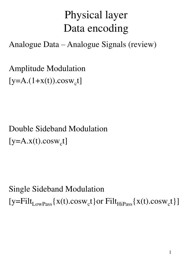
Physical layer Data encoding. Analogue Data – Analogue Signals (review) Amplitude Modulation [y=A.(1+x(t)).cosw c t] Double Sideband Modulation [y=A.x(t).cosw c t] Single Sideband Modulation [y=Filt LowPass {x(t).cosw c t}or Filt HiPass {x(t).cosw c t}]. Physical layer Data encoding.

E N D
Physical layerData encoding Analogue Data – Analogue Signals (review) Amplitude Modulation [y=A.(1+x(t)).coswct] Double Sideband Modulation [y=A.x(t).coswct] Single Sideband Modulation [y=FiltLowPass{x(t).coswct}or FiltHiPass{x(t).coswct}]
Physical layerData encoding Analogue Data – Analogue Signals (review) Frequency Modulation [y=A.cos(wct+k.x(t)] Phase Modulation [y=A.cos(wct+d(k.x(t))/dt]
Physical layerOther Digital Modulation Schemes Quadrature Phase Shift Keying (QPSK) 2 bits encoded per symbol => one of 4 different phase values
Physical layerOther Digital Modulation Schemes Quadrature Amplitude Modulation (QAM) 3 bits encoded per symbol one of 4 different phase values AND one of 2 different amplitudes
Physical layerOther Digital Modulation Schemes Spread Spectra (CDMA –DS, SS-FH)
Physical layerData encoding Non Return to Zero – Level (NRZ-L) Common, easy Could use 0=0Volts & 1=+Volts (eg TTL) => NRZ Usually use 0=+Volts & 1=0Volts • NRZ-L Easy to engineer DC component = ½ +Volts Won’t work with differential pair wiring (UTP) as cannot swap the common and signal wires Needs no synchronisation
Physical layerData encoding Non Return to Zero – Invert Ones (NRZ-I) A variation on NRZ-L Is a level that only changes for each ‘1’ data bit. The level as such does NOT necessarily represent a ‘1’ or a ‘0’ Is an example of differential encoding – more reliable to detect data in the presence of noise. If wires swapped (UTP) don’t lose encoding of ‘1’s and ‘0’s NRZ codes usually used in magnetic recording NRZ codes not suitable for long distance transmission
Physical layerData encoding Bipolar Alternate Mark Inversion (AMI) A ‘0’ is represented by 0Volts A ‘1’ is represented by alternating positive & negative voltages representing ‘1’s Average voltage on the line =0Volts No synchronisation needed Is an improvement over NRZ, BUT Inefficient - 3 levels for 1 bit Log2(3) = 1.58 So 1.58 bits of data needs to be transmitted to send 1 bit of the message
Physical layerData encoding Bipolar Alternate Mark Inversion (AMI) A ‘0’ is represented by 0Volts A ‘1’ is represented by alternating positive & negative voltages representing ‘1’s Average voltage on the line =0Volts No synchronisation needed Is an improvement over NRZ, BUT Inefficient - 3 levels for 1 bit Log2(3) = 1.58 So 1.58 bits of data needs to be transmitted to send 1 bit of the message
Physical layerData encoding Manchester Encoding (Manchester) Transition in the middle of each bit period • A low to high transition in the middle of the bit represents a ‘1’ • A high to low transition in the middle of the bit represents a ‘0’ No DC component +/- voltages used 2 levels represent 1 bit Twice the bandwidth required!
Physical layerData encoding Differential Manchester Encoding (Differential Manchester) Transition in each bit period • A transition at the beginning of the bit period represents a ‘0’ • The absence of a transition the start of the bit period represents a ‘1’ • The mid-bit transition represents the clocking information No DC component 2 levels represent 1 bit Twice the bandwidth required! Advantage of Differential encoding Self clocking
Local Area NetworksStandards IEEE standards 802.1 Overview 802.2 Logical Link Control 802.3 Ethernet CSMA/CD 802.4 Token Bus 802.5 Token Ring 802.6 Distributed Queue Dual Bus (DQDB) 802.11 Wireless FDDI - Fibre Distributed Data Interface
Local Area NetworksStandards IEEE 802.3 (thin Ethernet) standard RG58 cable 10base 2 configuration BNC connector on NIC Alt = RJ45 (for UTP cable) or DIX for thick Ethernet
Local Area NetworksStandards IEEE 802.3 (thin Ethernet) standard Electrical Characteristics 10Mbps Manchester encoding Slot time (or propagation delay) = 512 bits Interframe gap = 9.6msec Backoff limit = 10 Jam size = 32bits Max frame length = 1512 bytes Min frame length = 64 bytes