Download
1 / 22
220 likes | 353 Views
The Performance of An OTDM Demultiplexer Based on SMZ Switch. Razali Ngah, and Zabih Ghassemlooy Optical Communication Research Group School of Engineering & Technology Northumbria University, United Kingdom http: soe.unn.ac.uk/ocr/. Contents. Introduction OTDM All optical switches

E N D
The Performance of An OTDM Demultiplexer Based on SMZ Switch Razali Ngah, and Zabih Ghassemlooy Optical Communication Research Group School of Engineering & Technology Northumbria University, United Kingdom http: soe.unn.ac.uk/ocr/
Contents • Introduction • OTDM • All optical switches • Simulations and results • Conclusions
Introduction • Multiplexing:- To extend a transmission capacity • Electrical • Optical • Drawbacks with Electrical: • Speed limitation beyond 40 Gb/s (80 Gb/s future) of: • Electo-optics/opto-electronics devices • High power and low noise amplifiers • Bandwidth bottleneck due to optical-electronic-optical conversion Solution: All optical transmission, multiplexing, switching, processing, etc.
Multiplexing - Optical • Wavelength division multiplexing (WDM) • Optical time division multiplexing (OTDM) • Hybrid WDM-OTDM
OTDM • The total capacity of single-channel OTDM network = DWDM • Overcomes non-linear effects associated with WDM: (i) Self Phase Modulation (SPM) – The signal intensity of a given channel modulates its own refractive index, and therefore its phase (ii) Cross Phase Modulation (XPM) – In multi-channel systems, other interfering channels also modulate the refractive index of the desired channel and therefore its phase (iii) Four Wave Mixing (FWM) – Intermodulation products between the WDM channels, as the nonlinearity is quadratic with electric field • Less complex end node equipment (single-channel Vs. multi-channels) • Can operate at both: • 1500 nm • 1300 nm
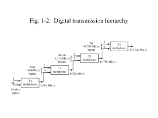
Data (10 Gb/s) Data (10 Gb/s) Rx Span N*10 Gb/s 10 GHz Rx Network node Light source N Rx Drop Add Clock Clock recovery Transmitter Receiver Fibre delay line Fibre Modulators Amplifier OTDM MUX OTDM DEMUX OTDM -Principle of Operation • Multiplexing is sequential, and could be carried out in: • A bit-by-bit basis (bit interleaving) • A packet-by-packet basis (packet interleaving)
All Optical Switches Terahertz Optical Asymmetric Demultiplexer (TOAD) Non-linear Optical Loop Mirror (NOLM) • Requires high control pulse energy and long fiber loop • Asymmetrical switching window profile due to the counter-propagating nature of the data signals
All Optical Switches – contd. Symmetric Mach-Zehnder (SMZ) • Symmetrical switching window profile • Integratable structure
All Optical Switches – contd. Comparative study of all optical switches [Prucnal’01]
SMZ Switch:Principle (i) No control pulses (ii) With control pulses
SMZ : Switching Window G1 and G2 are the gains profile of the data signal at the output of the SOA1 and SOA2, ΔФ is the phase difference between the data signals, and LEF is linewidth enhancement factor
SMZ :Switching Window (simulation) TABLE I. SIMULATION PARAMETERS Parameter Value SOA . LengthLSOA 0.3 mm . Active area, 3.0x10⁻¹³ m2 . Transparent carrier density, No 1.0x1024 m-3 . Confinement factor, 0.15 . Differential gain, g 2.78x10²⁰ m2 . Linewidth enhancement, 4.0 . Recombination coefficient A 1.43x10⁸ 1/s . Recombination coefficient B 1.0x10⁻¹⁶ m3/s . Recombination coefficient C 3.0x10-41 m6/s . Initial carrier density 2.8x1024 m-3 . Total number of segments 50 Data and control pulses . Wavelength of control & data 1550 nm . Pulse FWHM 2 ps . Control pulse peak power 1.2 W . Data pulse peak power 2.5 µW
SMZ :Switching Window (comparison) Theoretical Simulation
SMZ :On-Off Ratio • The ratio of the output power in the on-state to the output power in the off-state Input signal of the SMZ Transmitted output of the SMZ
SMZ :On-Off Ratio – contd. On-off ratio at different data rate On-off ratio and normarlised transmission power Against linewidth enhancement factor
Receiver parameters ___________________________________ Parameter Value Pre-amplifier Mode Gain controlled Noise Figure 4 dB Gain 25 dB PIN detector Responsivity 1 A/W Thermal noise 10 pA/Hz1/2 Cutoff frequency 7.0x10⁹ Hz __________________________________________ SMZ :BER Performance
SMZ :BER Performance – contd. BER against the average received power for (a) back-to-back without demultiplexer, (b) 40 – 10 Gb/s demultiplexer, (c) 80 – 10 Gb/s demultiplexer and (d) 160 – 10 Gb/s demultiplexer
SMZ :BER Performance – contd. Comparison with experimental results
( a) ( c) (e) Port 1 (f) SMZ1 SMZ2 SMZ3 (clock (read (route extract) address) payload ) ( b) Port2 (d) (a) OTDM Signal (b) Extracted Clock (c) Address + Payload (d) Address (e) Payload (f) Payload Application of SMZ switch: 1x2 All OTDM Router
Conclusions • An all optical demultiplexer based on SMZ has been implemented in a simulation environment using VPI. • BER analysis has been performed. • The power penalty of the demultiplexer is mainly due to the ASE noise in the SOAs of the SMZ. • The application of low noise SOA will reduce the power penalty. • An all optical demultiplexer based on SMZ has been implemented in a simulation environment using VPI. • Simulation results show a small power penalty of 0.7 dB for the system with all optical SMZ demultiplexer compared with the system without a demultiplexer. • An all optical demultiplexer based on SMZ has been implemented in a simulation environment using VPI. • Simulation results show a small power penalty of 0.7 dB for the system with all optical SMZ demultiplexer compared with the system without a demultiplexer.
Acknowledgement • Thanks to the University of Teknologi Malaysia for sponsoring the research.