Download
1 / 10
130 likes | 313 Views
An Integrated MEMS-BiCMOS SINCGARS Transceiver. Demonstration Schedule Monday, June 5th 12-1PM and 5-6PM Tuesday, June 6th 3-4PM Wednesday, June 7th 5-6PM. Design Automation Conference, June 2000. Michael McCorquodale, Ark Wong, Karthik Nagarajan, Haluk Kulah, Clark T.-C. Nguyen

E N D
An Integrated MEMS-BiCMOS SINCGARS Transceiver Demonstration Schedule Monday, June 5th 12-1PM and 5-6PM Tuesday, June 6th 3-4PM Wednesday, June 7th 5-6PM Design Automation Conference, June 2000 Michael McCorquodale, Ark Wong, Karthik Nagarajan, Haluk Kulah, Clark T.-C. Nguyen Center for Integrated Microsystems Department of Electrical Engineering and Computer Science University of Michigan Ann Arbor, Michigan 48109- 2122
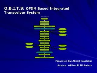
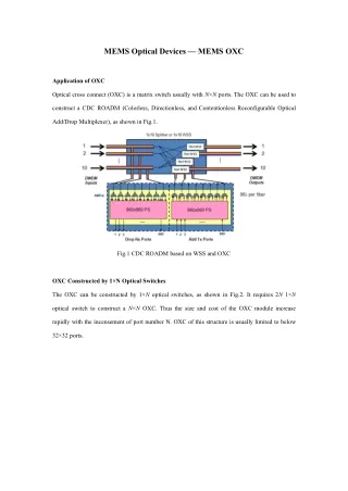
MEMS Filter Antenna Signal Power MEMS Filter MEMS Filter MEMS Filter MEMS Filter MEMS Filter MEMS Filter MEMS Filter MEMS Filter MEMS Filter MEMS Filter MEMS Filter MEMS Filter MEMS Filter MEMS Filter MEMS Filter w RF Channel Selection with MEMS Desired Information Signal Antenna Signal Power w Front-End filters significantly reduce interfering signals prior to subsequent electronics Channel selection achieved by simply activating the correct filter
Vertically-Driven Clamped-Clamped mResonator To date, most used design to achieve VHF Smaller mass higher frequency range
Free-Free Beam mMechanical Resonators Effectively removes anchor dissipation by removing the anchors themselves
Fabricated PolysiliconFree-Free Beam mResonator Beam Length = 14.3mm Support Length = 13.3mm fo = 71.5MHz Q = 8,250 Quarter-Wavelength Torsional Beam Drive Electrode 1 m 13.3 m 14.3 m Flexural-Mode Beam Ground Plane and Sense Electrode Anchor Anchor
Conclusions • Demonstrated advantages of RF channel selection • Compared proposed architecture to typical architecture • Demonstrated clamped-clamped and free-free beam resonators • Reported typical performance parameters for free-free devices