Download
1 / 29
290 likes | 387 Views
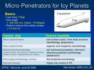
Penetrators for TSSM. Rob Gowen on behalf of UK Penetrator Consortium. MSSL/UCL UK. TSSM Meeting - Monrovia, Jun 02 2008. Micro-Penetrators. Basics : Low mass [~5Kg] Very tough [~ 200-500 m/s, impact ~10-50kgee] Perform science from below surface [~0.5-few m]. 2 kg payload. 5 kg.

E N D
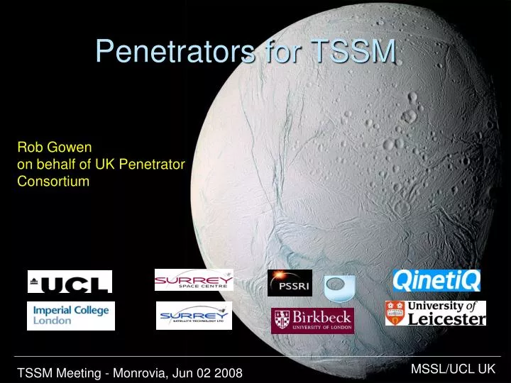
Penetrators for TSSM Rob Gowen on behalf of UK Penetrator Consortium MSSL/UCL UK TSSM Meeting - Monrovia, Jun 02 2008
Micro-Penetrators • Basics: • Low mass [~5Kg] • Very tough [~ 200-500 m/s, impact ~10-50kgee] • Perform science from below surface [~0.5-few m] 2 kg payload 5 kg
Impact Trial19-21 May 2008 • Full-scale trial • 3 Penetrators, ~0.6m long, ~13kg, Aluminum • 300m/s impact velocity • Normal Incidence • Dry sand target 0.56m
Impact trial – Payload Mass spectrometer Radiation sensor Batteries Magnetometers Accelerometers Power Interconnection Processing Micro-seismometers Accelerometers, Thermometer Batteries,Data logger Drill assembly
Impact Trial Objectives Demonstrate survivability of penetrator shell, accelerometers and power system. Assess impact on penetrator subsystems and instruments. Determine internal acceleration environmentat different positions within penetrator. Extend predictive modelling to new impact and penetrator materials. Assess alternative packing methods. Assess interconnect philosophy.
Trial Hardware Inners Stack
Impact Trial - Configuration • Rocket sled • Penetrator
Target • Dry sand • 2m x2m x6m • Small front entrance aperture (polythene)
1’st Firing - Results • Firing parameters: • Impact velocity: 310 m/s • (c.f. 300m/s nominal) • Nose-up ~10degs (c.f. 0 degs nominal) • => worst case • Penetrator found in top of target • Glanced off a steel girder which radically changed its orientation. • Penetration: ~3.9m • Much ablation to nose and belly • Rear flare quite distorted. • Penetrator in one piece ✓
1st Firing – internal Results Micro seismometer bay Connecting to MSSL accelerometer and data processing bay
1’srt Firing – QinetiQ accelerometer data Initial impact hi-res: Tail slap peak Overview: 5 kgee smoothed, ~16 kgee peak high frequency components ~5khz
1’st Firing – MSSL accelerometer data 11 kgee Peak gee forces in rear of penetrator Along axis: • Cutter: 3kgee • Main: 10kgee • Girder: 1kgee Along axis cutter Main impact Girder 15 kgee Vertical axis 4 kgee Horizontal axis
Hi-res MSSL accelerometer data Lots of high frequency structure
2nd Firing “Jaws-3?” ..struck steel girder and moved it 6 inches
2nd & 3rd Firings • All 3 firings remarkably consistent ~308-310m/s velocity, and ~8-10 degs nose up. • 2/nd firing penetrator hit steel beam square on. • Penetrators survived all 3 firings. Payload still operational. Steel nose for 3rd firing
Survival Table Triple worst case: exceed 300m/s, >8deg attack angle No critical failures– currently all minor to unprotected bays or preliminary mountings
Impact Trial Objectives Demonstrate survivability of penetrator body, accelerometers and power system. Assess impact on penetrator subsystems and instruments. Determine internal acceleration environmentat different positions within penetrator. Extend predictive modelling to new penetrator materials,and impact materials. Assess alternative packing methods. Assess interconnect philosophy.
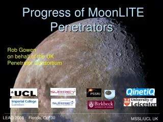
Next Steps & Strategy … • Next trial – aiming for Jan’09. • impact into harder material (ice,icysand,concrete) • full-up system (all operating) • transmit from target • Parallel supporting studies Strategy: in parallel • Major developments for Lunar (MoonLITE) mission • Delta developments for icy planets
Penetrators Conclusions • Acheived major step in demonstrating confidence in technology • Including impact survival into dunes & fluvial material - > next steps for harder materials and establishing larger engineering margins. • No great history of failure - only 1 planetary delivery to date • Significant TRL with previous space qualified technology • A useful tool in the toolbox of planetary exploration • Capable of addressing fundamental astrobiology signatures and habitability • Provide ground truth & new information not possible from orbit • Provide useful landing information for future missions. Penetrator website: http://www.mssl.ucl.ac.uk/planetary/missions/Micro_Penetrators.php email:rag@mssl.ucl.ac.uk
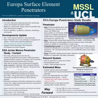
Detachable Propulsion Stage Point of Separation PayloadInstruments PDS (Penetrator Delivery System) Penetrator What are Penetrators ? • Low mass projectiles ~5Kg+PDS for Enceladus • High impact speed ~ 200-500 m/s • Very tough ~10-50kgee • Penetrate surface ~ few metres • Perform science from below surface
Penetrator Payload/Science A nominal 2kg payload … • Accelerometers – Probe surface/sub-surface material (hardness/composition) • Seismometers - Probe interior structure (existence/size of water reservoirs) and seismic activity of bodies • Chemical sensors – Probe surface refactory/volatile (organic/ astrobiologic) chemicals, perhaps arising from interior. • Thermal sensors - Determine subsurface temperatures and possibly probe deep interior processes. • Mineralogy/astrobiology camera – Probe surface mineralogy and possible astrobiological material. • + other instruments – to probe surface magnetic field, radiation, beeping transmitter, etc… • descent camera (surface morphology, landing site location, etc)
Enceladus - Science/Technology Requirements • Target • E.g. region of upwelled interior material. • 2 penetrators would allow additional target, improved seismic results and natural redundancy but require 2xmass. • Lifetime • Only minutes/hours required for camera, accelerometer, chemistry, thermal & mineralogy/astrobiologic measurements. • An orbital period (~few days) for seismic measurements. (requires RHU) • Spacecraft support • ~7-9 years cruise phase, health reporting • Delivery • Targetting precision. • Ejection, descent motors & orientation, pre-impact separation, communications, impact. • Operation • Power/thermal (battery/RHU), data handling, communications.
Preliminary Mass Estimates (*) heavy penalty for Enceladus delivery: estimate ~8x(penetrator mass) with deployment from Titan with ∆V~3.7Km/sec
Lunar-A and DS2 space qualified. Military have been successfully firing instrumented projectiles for many years to comparable levels of gee forces into concrete and steel. 40,000gee qualified electronics exist (and re-used). Currently developing similar penetrators for MoonLITE. Payload heritage: Accelerometers, thermometers, sample drill – fully space qualified. Seismometers (ExoMars) & chemical sensors (Rosetta) heritage but require impact ruggedizing. Mineralogy camera – new but simple. Heritage When asked to describe the condition of a probe that had impacted 2m of concrete at 300 m/s a UK expert described the device as ‘a bit scratched’!