Download
1 / 15
150 likes | 157 Views
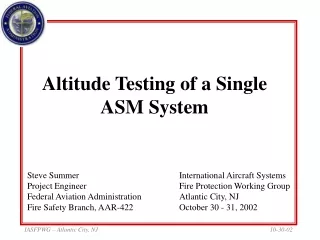
Altitude Testing of a Single ASM System. Steve Summer Project Engineer Federal Aviation Administration Fire Safety Branch, AAR-422. International Aircraft Systems Fire Protection Working Group Atlantic City, NJ October 30 - 31, 2002. Objectives.

E N D
Altitude Testing of a Single ASM System Steve Summer Project Engineer Federal Aviation Administration Fire Safety Branch, AAR-422 International Aircraft Systems Fire Protection Working Group Atlantic City, NJ October 30 - 31, 2002 IASFPWG – Atlantic City, NJ
Objectives • Obtain static data of a single ASM system’s output operating in both a HF/LP and LF/HP mode. • Obtain dynamic data of a single ASM system’s output throughout a given flight profile operating in a LF/HP mode during ascent and cruise and a HF/LP mode during descent. • Compare data with predictive model output. IASFPWG – Atlantic City, NJ
Controlled Parameters • Inlet pressure • Controlled via a manual pressure regulator • Inlet air temperature and purity • Controlled to 180 ± 10 ºF via M750 and secondary air circulation heater • Ambient pressure • Controlled via environmental chamber and manual dive port • Orifice Sizes • Controlled via needle valves, set to desired sea level NEA concentrations IASFPWG – Atlantic City, NJ
Measured Parameters • NEA output flow • Measured by an insertion mass flow meter • NEA output purity • Measured by O2 analyzer • Pressure drop across the membrane • Measured by DP meter • Pressure drop across the orifice • Calculated as DPor = Pin - DPmem - Pamb IASFPWG – Atlantic City, NJ
Test Plan • Size the LF/HP orifice to give an output of 5% O2 at SL conditions. • Size the HF/LP orifice to give an output of 11% O2 at SL conditions. • Conduct tests operating under both flow conditions at incremental altitudes up to 42 kft. • Simulate a representative flight profile, controlling ambient and ASM inlet pressure. IASFPWG – Atlantic City, NJ
Static Data Results IASFPWG – Atlantic City, NJ
Flight Simulation Results IASFPWG – Atlantic City, NJ
Conclusions • The system performed favorably at static points and throughout a given flight simulation. • High flow conditions produced NEA flow and purity data consistent with predictive model output. • Some corrections need to be made to the predictive model under low flow conditions. IASFPWG – Atlantic City, NJ