Download

1 / 35
420 likes | 702 Views
Manufacturing Processes lab I Running a lathe machine. Machining. Machining – material removal by a sharp cutting tool , e.g., turning, milling, drilling Cutting action involves shear deformation of work material to form a chip. (As chip is removed, new surface is exposed). Turning.

E N D
Machining • Machining –material removal by a sharp cutting tool, e.g., turning, milling, drilling • Cutting action involves shear deformation of work material to form a chip. (As chip is removed, new surface is exposed)
Turning • Turning refers to cutting as shown in this figure. • Single point cutting tool removes material from a rotating workpiece to form a cylindrical shape.
Cutting Conditions for Turning Speed, feed, and depth of cut in turning.
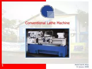
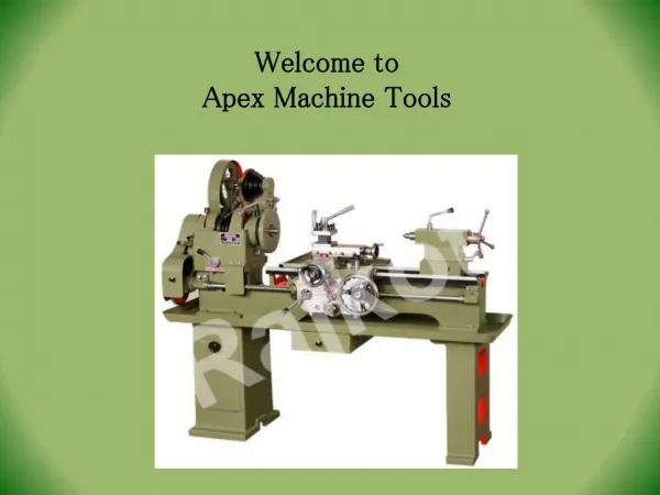
Turning: Engine Lathe • Turning is another of the basic machining processes. • Turning is performed on a machine called a lathe in which the tool is stationary and the part is rotated.
Turning: Engine Lathe • The figure illustrates an engine lathe. • Lathes are designed solely for turning operations, so that precise control of the cutting results in tight tolerances. • The work piece is mounted on the chuck, which rotates relative to the stationary tool.
Engine Lathe Carriage • The figure below illustrates the carriage of an engine lathe. The carriage allows cross-feed and diagonal movements in addition to axial movement.
Chucks • The chuck is integral to a lathe's functioning because it fixtures the part to the spindle axis of the machine. Below is shown a three-jaw chuck with jaws that are all driven by the same chuck key. This arrangement provides convenience in that parts can be mounted and dismounted quickly. • 3 and 4-jaws chuck: It is easier to align the work piece axis with the lathe axis which has 4 jaws chuck.
Engine Lathe Tail Stock The tail stock of an engine lathe is used to provide a fixture at the end of the part opposite from the chuck. The tail stock can be used to support a long, thin part so that more radial cutting force can be applied and higher rotational speeds can be attained without a "whipping" instability effect.
Engine Lathe Tail Stock Drill bits can be fixtured in the tail stock to cut axial holes in a turned part. These central holes are more accurate than a drill press or mill could provide since the lathe is dedicated to operations in which an axially-symmetric part is rotated about its central axis. The fixturing is more accurate since all fixturing is based upon surfaces of revolution about the central axis, and the machining is more rigidly supported for the same reason.
Tool • The tool inserted in the tool holder is shown below:
Tool post The tool postcan pivot the tool about a vertical axis and the cutting tool can be moved in and out along its long axis. The cutting tool is held in by the vertical screws, the heads of which can be seen above the cutting tool groove.
Turret tool post This tool post can hold many tool bits at the same time. Each cutting tool can quickly be swiveled into cutting position and clamped into place using a quick clamping handle.
Parting Tool • This figure shows how a parting tool is fixed and used. • Parting is important at the end of a turning process in order to separate the part from the raw material. • Parting must be carried out slowly and carefully since the tool is quite long and is prone to vibrating. • Parting is not very accurate, and a finishing cut must often be undertaken after parting if the parted surface is to be accurate.
Facing • The term "facing" is used to describe removal of material from the flat end of a cylindrical part, as shown below. • Facing is often used to improve the finish of surfaces that have been parted. Tool is fed radially inward
Threading • Pointed form tool is fed linearlyacross surface of rotating workpart parallel to axis of rotation at a large feed rate, thus creating threads
Reaming • Used to slightly enlarge a hole, provide better tolerance on diameter, and improve surface finish
Knurling • Knurling is an operation used to produce a texture on a turned machine part. Handles are often knurled in order to provide a gripping surface. The two wheel inserts shown on the tool below contact the work piece, and with pressure, cold-form a pattern into the surface of the part.
Boring is rather well named... its, urm, quite boring. Essentially you have to drill a hole into the job with your biggest drill bit - Then you have to mount the boring tool on the tool post so that it is parallel to the ways. Then you use the tools to slowly increase the inside diameter of the job to the size you require. The most you can take off in each pass is about 0.5mm - so it can take a long time to make a 2 inch bore hole! Boring • The boring tool is fixed in the tail stock. • Boring can be accomplished on a mill or even a drill press, but is most accurate on a lathe, because the fixturing is relative to the central spindle axis
Boring The length of the boring bar is of critical importance because of its tendency to bend.
Turning categories Below are illustrated some of the many types of machining that can be accomplished on a lathe.
Single-Point Cutting Tool Variety • Single-Point Cutting Tool Variety • There are many types of cutting tools for different operations. Below is shown a few of the variety, here shown with a tool holder adapter that fits into a larger tool post fixture.
Single-Point Cutting Tool Variety • Below is shown how single-point lathe tools can be used.
Test yourself! • Turning is performed on a machine called a lathe in which the part is stationary and the tool is rotated. • True • False • You mount your work piece inside the chuck not a tail stock. • True • False
Test yourself! • Which part of lathe machine is this? Chuck
Boring Test yourself! • Which operation is shown here:
Test yourself! • Which operation is this? Facing Tool is fed radially inward
Test yourself! • What is the name of this operation: knurling
Test yourself! • Name different operations shown here: parting Boring Facing