Download
1 / 29
300 likes | 458 Views
Whistler Wave Launch and Diamagnetic Plasma Formation in Laboratory Experiments Bill H. Quon, Microwave Plasma Applications 252 S. Poplar Ave # 403 Brea, CA 92821 email: bquon1@msn.com.

E N D
Whistler Wave Launch and Diamagnetic Plasma Formation in Laboratory Experiments Bill H. Quon, Microwave Plasma Applications 252 S. Poplar Ave # 403 Brea, CA 92821 email: bquon1@msn.com
Whistler waves are accessible forpropagating into and heating the high density plasma The RHCP Whistlers can be excited into both low and high density plasma by launching from high magnetic field (ce/ > 1). These waves do not go across the R-cutoff layer, and pass the L-cutoff without being affected. The accessibility problem arises in the vicinity of the boundary pe/ = 1. The CMA diagram shows that the RHCP waves propagation along B will pass this boundary, but those perpendicular to B will be reflected. M
Whistler Wave Launched from the High Magnetic Field Propagates into Over-Dense Laboratory Plasma Power dissipation Increases with plasma density increases. No abrupt changes in reflectivity pattern observed in vicinity of the pe =o boundary. The maximum plasma density achievable for a given system depends only on power and neutral feed available. Both power reflection and power transmission became negligibly small at high plasma density. After J. E. Stevens, “Electron Cyclotron Plasma Sources” In “high Density Plasma Source”, edited by O. A. Povov.
Electrons can be heated by electromagnetic waves near the electron cyclotron resonant zone ECR condition: ce in uniform B. • For whistler waves, the resonance condition requires • - ce - kz vz 0 • Strong absorption occurs for those electrons moving backwards kz vz (-ce) < 0.
Whistler waves were launched from the maximum B with Teflon filed C-band waveguide horn at 2.45 GHz in AMPED ce =o 40. 80. cm 0.
Exponential increase of energetic electron current was observed when the heating is moved to the flat field region. B=875 G
Compact Tabletop ECR with Whistler Wave Coupling Tokyo Electron Phoenix Laboratories
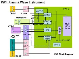
Whistler Wave Excitation in Compact ECR WR430 Coupler Neodymium Magnet AlN-Wave window ECR Chamber Iron Pole Piece Plasma Pump Baffle Adjustable Magnet Pressure Recovery Baffle Main Vacuum Chamber
Example of whistler wave absorption in ECR zone Measured waveform in ECR plasma by Quon & Dandl (1989) The wavelength of the RHCP wave decreases as the wave approaching resonance. Strong absorption occurs before the wave actually reaching the resonance layer.
Over-Dense Plasma Productions in ECR with Whistler Wave L = 20 cm P = 0.1 - 10 m Torr Te = 8.0 - 2.3 eV P = 6 kW A = 100 cm2 P/A = 60 W/cm2 n = 1 - 2 x1013 cm-3 Plasma density 1-2 x 1013 cm-3 are predicted in pressure range 0.1 to 10 m Torr from particle and power balance ECR model of Dandl and Guest and Lieberman et. Al. The measured maximum plasma density exceeds 5x1013 cm-3 at the ECR layer. x12
Electron Run-away in Low Pressure Operation of ECRH Systems At low neutral gas pressure, p < 10-5 Torr ECR plasmas do not achieve very high plasma density, but have relatively higher electron temperature. The electron energy distribution function usually contain large energetic electron components.In magnetic mirror confinement systems, electrons are runaway to relativistic energy. The energetic electrons appear to be heated at the relativistic electron cyclotron resonance condition: = ce = eB/mc The resonance moves to higher B. Multiple frequencies and upper-off resonance heating were found to have strong effects.
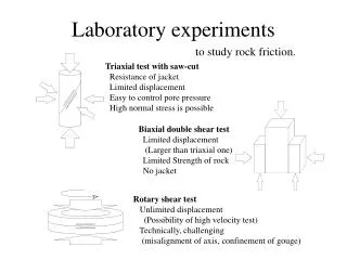
Diamagnetic field profiles were measured to reconstruct the spatial distribution of diamagnetic plasma Magnetic field profiles of the diamagnetic current were measured using axial and radial Hall probe arrays. Experimental arrangement
The 2-D spatial pressure distribution was reconstructed using equilibrium code with the measured diamagnetic field data. The pressure created a local magnetic minimum in the total magnetic field. The magnetic field contour suggested the hot electrons are trapped in the minimum of the local magnetic mirror. The majority of the hot population appeared to be heated by the applied frequencies at the localtion where = 2 ce
The pressure profiles were measured as function of time. The pressure profiles measured during the build-up time indicated the hot electrons are slashing back-and forth in the flux tube, giving a pressure peak at their turning points in the mirror field.
The ELMO Produced ECRH Plasma with 500 keV Electrons B=20 kG f = 35 GHz P= 800 W. no~ 1012 cm-3 nc~ 1011 cm-3 Tc~ 100 eV nh~ 1012 cm-3 Th~ 500 keV Estimated Ring Paramters: 4 cm thick 9 cm diameter 10 cm long = nT/4B2 ~ 1 After R. A. Dandl et al., Phys. Fluids, 9:1498 (1966)
Summary of Presentation Effective electron heating can be achieved by launching the Whistler wave into the resonance zone from the high field side of the magnetic system. At high pressure and high heating power, very high plasma density can be produced. The heating efficiency is higher with higher electron temperature so molecular excitation can be reduced. At low pressure energetic electrons are generated. When confined by magnetic field mirror, the hot electron population can build up to a plasma pressure that is significant compared with the magnetic field pressure. The magnetic moment of the localized plasma can be very large: M = IxArea = NT/B.
ELF/VLF Excitation by Pulsed HF Power at the Electron Cyclotron Resonance Our goal is to generate a large plasma magnetic dipole moment below or above 100 km above HIPAS. The ELF/VLF magnetic field produced can be sensed around the world through the earth-ionosphere-waveguide.
The RHCP wave power is completely absorbed at the ECR zone while the LHCP wave is reflected at the L-Cutoff boundary >p >p <p <p Ray tracing for the electromagnetic waves satisfying the Appleton Hartree dispersion relation
Electron Heating by Electron Whistler Wave Against Electron-Neutral Collisions Electron heating in single pass of electron Cyclotron Resonance: E = (Zo/(ck/)*P/A)1/2 = Min (e-n, res, 0 ) v = e/m E T = ½ e2/mE2 2 e-n = 10-5 sec (collision) res = 10-4 sec (Resonance) 0 = 10-4 sec (Pulse) The electron-neutral collision time e-n 10-5 sec at about 100 km altitude in the E-layer where the normal electron temperature is cold, Te = 0.03 eV (300 K). The electrons must gain enough energy (T > 20 eV) in a time short compared to e-n such to minimize excitation energy loss. It requires about 20 mW/m2 of the HF power flux to bring the electrons to the ionizing energy level by electron cyclotron resonance heating in the ECR layer.
Pulsed HF Power Will be Used for Electron Accelerations Frequency: f = 1.4 MHz Plasma Parameters ne = 10000 cm-3 Vacuum Electric Field Eo = 4 V/m ( = 128 mW/m2 ) Refraction Index n = 3.4 Plasma Heating Field E = 4.3 V/m Minimum Collision Time: min 1 x 10⁻⁵ sec. Energy Gain (per pass) T = 46.9 eV The 4 V/m electric field requires a power flux, = 21.3 mW/m2, or 2.7 GW ERP. This power level will be available from pulsed transmitters currently under development at HIPAS Observatory.
Creating High Density Plasma by electron Impact Ionizations The energetic electrons created by HF ECR are capable of ionizing the background neutral particles in a fast time scale, I.e. 10-5 sec. Plasma produced will be localized in the heating region for a time scale of electron-ion recombination time, I.e. ~100 sec. Thus a very high density plasma can be created using multiple HF pulses in a time scale of the recombination time.
Excitation LHCP Ion Cyclotron Waves by Modulation of the Diamagnetic Dipole at ELF/VLF with AM HF Power. The LHCP ion cyclotron waves are similar to the RHCP electron whistler waves. They can be excited using a dipole loop antenna inside the plasma. M/m V B • • E k E k B Bo
B Magnetic field profile MPD-1 Schematic Q-machine Phase 1 Collector/Probe 300 Phase 2 0.6 mm 60 1560 Collector 8.5 mm 7 mm EXPERIMENTAL SET-UP Grid Insulator Fence