Download
1 / 41
410 likes | 479 Views
Lecture 09: Ray Casting. COMP 175: Computer Graphics March 11, 2014. Motivation. So far, you have learned to build a “passive” renderer Input: vertices and geometric shapes Output: an image What happens when a user wants to manipulate the objects in the scene?

E N D
Lecture 09:Ray Casting COMP 175: Computer Graphics March 11, 2014
Motivation • So far, you have learned to build a “passive” renderer • Input: vertices and geometric shapes • Output: an image • What happens when a user wants to manipulate the objects in the scene? • Say, a user clicks on an object on screen, how do you know: • A. which object the user clicked on? • B. where on the object the user clicked on?
Origin of Ray Casting / Ray Tracing • Albrecht Dürer, 1525 • http://www.youtube.com/watch?v=8s1LzIrWbE8 • Durer: record string intersection from center of projection (eye) to the object as points on a 2D plane. • Points created are perspective projection of 3D object onto 2D plane
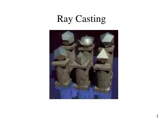
What is a Ray Tracer? • A ray tracer is a mapping of rays from the camera (eye) through each pixel to the objects in the scene • Each pixel returns either: • Ray intersection with the nearest object in the scene • No intersection • Unlike Durer’s method, a typical ray tracer also takes into account of lighting (and material) information • To render a scene, a ray is cast from each pixel, and the returned value (color) is recorded.
Ray Tracing Fundamentals • There are three parts to a ray tracer: • Generating rays • Shoot a ray from the eye through a sample point on the film plane that corresponds to a pixel • Repeat the process for each pixel • Ray-Object intersection • For each object in the scene, compute their intersection point (if one exists) • Record the closest intersection point to the eye • Calculate lighting (i.e. color) • Use illumination model to determine direct contribution from light sources • (For recursive ray tracer), recursively generate secondary rays that might contribute to the color of the pixel (e.g., reflective surfaces or mirrors need to reflect other objects in the scene)
Ray Tracing vs. Scan Conversion • How is ray tracing different from scan conversion? • Shapes and SceneView both use scan conversion to render objects in a scene and follow the pseudocode: for each object in the scene for each triangle in the object pass vertex geometry and colors to OpenGL tell OpenGL to render/map the triangle onto screen
Ray Tracing vs. Scan Conversion • Ray tracing uses the following pseudocode: for each sample (pixel) on the film plane 1. determine the closest object in the scene hit by a ray through that pixel 2. set the color based on the calculation of the illumination model for the intersected object • Note the distinctions: • Ray tracing iterates over PIXELS • Scan conversion iterates over VERTICES
Step 1: Generating a Ray (Solution 1 – World Coord) • Ray Origin • Let’s look at the geometry in the world space coordinate • We’ll start the ray from the camera’s position (eye point). Call that point P • Shoot a ray from P towards a point on the film plane (which can be thought of as the UV plane in the camera’s UVN (or UVW) space). Call this directional vector d. • In parametric form, any point along the ray can be described using this form: P + td, where: • P is the ray’s origin (eye point) • d is the unit vector in the direction of the ray • t is a non-negative real value
Step 1: Generating a Ray (Solution 1 – World Coord) • We know the value of the eye point, but what about the look direction? • Consider the simple case: • Finding the look direction means finding the “look at” point, call it Q, then the ray direction is just: d = normalize(Q-P) • Recall that P is the eye point • If Q is right on the look vector, that’s pretty straight forward: Q = P + nearPlane* lookV Q
Step 1: Generating a Ray (Solution 1 – World Coord) • Now that we have the point Q, can we find this other point S? • S = Q + au + bv • How do we find a and b? S Q (a, b) S Q
Step 1: Generating a Ray (Solution 1 – World Coord) • First, we need to find the width (W) and height (H) of the film plane in the world coordinates: • If we place the film plane on the near clipping plane, let’s say that the plane extends from –W to W in the u direction, and –H to H in the v direction • For a view angle of , and the aspect ratio of (w/h) • and (a, b) S Q
Step 1: Generating a Ray (Solution 1 – World Coord) • Given H and W, finding a and b is pretty easy: (a, b) S Q
Step 1: Generating a Ray (Solution 1 – World Coord) • The origin of a ray is at the eye point P • The direction of the ray is S– P, where S is a 3D point on the film plane. • S has the form of Q + au + bv • Q is P + near*LookV
Step 1: Generating a Ray (Solution 2– Camera Coord) • The second approach to computing a ray is to think of the ray in the camera’s own coordinate system. • In this system, the camera’s position is at the origin (0, 0, 0), and the look vector is always –z (0, 0, -1) • The four corners of the far plane have the coordinates of (-1, 1, -1), (1, 1, -1), (-1, -1, -1), (1, -1, -1) canonical view volume Any plane z = k, -1<= k < 0 can be the film plane
Step 1: Generating a Ray (Solution 2 – Camera Coord) • In this coordinate system, finding the lookAt point is pretty easy. The x value ranges from [-1, 1], and the y value ranges from [-1, 1]. The z value is always -1. • So the lookAt point will have the form of (-1+2/nCols, -1+2/nRows, -1) • Once we have the lookAt point, we need to apply the inverse of the camera’s normalization matrices. • Recall that in building a synthetic camera, we map the camera in world coordinate into the camera’s coordinate space. The steps are: • Translate, Rotate, Scale, Unhinge () • Here, we do not need to do the Unhinge step, but we do need to invert the first three parts: • UnScale, UnRotate, UnTranslate ()
Step 1: Generating a Ray (Solution 2 – Camera Coord) • Remember that we need to apply this inverse matrix to the two points that make up the ray • The eye point P • The point on the far plane • Don’t forget to normalize the resulting ray vector
Step 1: Generating a Ray (Solution 2 – Camera Coord) • In Summary: • Start the ray at center of projection (“eye point”) • Map 2D integer screen-space point (x, y) onto 3D film plane • scale x, y to fit between -1 and 1 • set z to -1 so points lie on the far clip plane • film plane = far clip plane when z = -1 • Transform 3D film plane point (mapped pixel) to an untransformed world-space point • need to undo normalizing transformation • Construct the direction vector • point minus point is a vector • direction = (world-space point (mapped pixel)) – (eye point (in world space))
Ray-Object Intersections • How do we determine if (and where) two mathematical objects intersect? • For example, how do we know where two lines intersect? • y = 3x + 1 • y = 2x + 4 • In concept, the two objects intersect where their values are the same. In this case, we can say • 3x + 1 = 2x +4 • x = 3 • put back into either equation, we get y = 10 • So the two lines intersect at (3, 10)
Ray-Object Intersection • Intersection between a ray and a 3d geometric object is the same. • We know the mathematical definitions for sphere, cylinder, cube, and cone. • We also know the mathematical definition for a ray • This is from your Assignment 1 -- more on this later • However, in our scene graph, our 3d object can be: translated, rotated, and scaled… • It’s a pain when the mathematical definition of the object is different for every object in the scene!
“Fixing the Frame of Reference” • For example, in the original problem with 2 lines, we might be able to “fix” one of the equation so that it’s always easily solvable. For instance, let’s say that we want one of the equation to always be: • y = 0 • Then, in our original equations • y = 3x + 1 • y = 2x + 4 • We would then: • Subtract 1 from both equations (shift both lines down by 1) • For both equations, divide both sides by 3x • Subtract 1 from both equations • This results in: • y/x = 0 • y/x = -1/3 + 1/x • Now we can solve for x
In 3D • Our trick is basically the same – we want to solve intersection for each “Shape” once, and we do this in the Object Coordinate Space where: • The object is always centered at (0, 0, 0) • The object is not rotated • The object is bounded within -0.5 to 0.5 in x, y, and z directions • This means that we need to transform the ray from World Coordinate Space into Object Coordinate Space
Example • In Assignment 3 (SceneView), after “flattening” the scene graph hierarchy, each object is associated with a single 4x4 transform matrix, M • This matrix is an Object to World transform (transforms from the object space to the world space) • If this is confusing, think about how the point (0, 0, 0) gets transformed after multiplying by this matrix… This implies that the origin in object coordinate space gets mapped to the a point in the world coordinate • Since our ray is in the World Coordinate Space, we need to invert M such that the matrix goes from World to Object coordinates
Ray from World to Object Coordinate • Recall that our ray is defined by two components: • The eye point P • The direction • This means that converting the Ray from World Coordinate into Object Coordinate requires two transforms:
Intersection in Object Space • Now that we have the Ray in the Object Coordinate: • Given a t value, this equation describes a 3D point in the object coordinate space: • Then we can describe our 3d geometric objects in the same way that we did in Assignment 1, in that our equation can assume: • Object is at 0, 0, 0 (no translation) • Object is not deformed in some way (no scaling) • Object is axis-aligned (no rotation. Think cube)
Example: Sphere • The equation for a 3D sphere is: • Where r is the radius of the sphere • dx, dy, and dz represent the center of the sphere • Using vector notation, we can rewrite this as: • Where is any given point on the surface of the sphere • is the origin of the sphere • The double bar means to take the length of the vector
Ray – Sphere Intersection • Recall that to find intersection between two mathematical objects, we just have to set the two equations to be equal… • Our two equations are: • Ray: (note, this is in object space) • Sphere: • Substitute into the Sphere equation: • We can drop because it is (0, 0, 0) in the object space • Recall that the (square of the) length of a vector is the same as the dot product of the vector onto itself • If this is unclear, think about what the dot product is • Now we can rewrite the equation as
Ray – Sphere Intersection • From the last slide: • Multiply it out, we get • , or • This should look familiar as this is a simple quadratic equation . In our case: • Our goal is to solve for t:
Algebra Reminder • There are a few things about this equation that should be familiar to you: • The discriminate () should be positive, otherwise there is no real solution • There are two solutions (because of the + and -) • Both properties are meaningful in our solution: • If the discriminate is negative, there is no solution • In this case, the ray misses the sphere – there is no intersection • If the discriminate is 0, we have one solution • In this case, the ray “grazes” the sphere (and ray becomes a tangent to the sphere) • If the discriminate is positive, we have two solutions • The two solutions represent the two points where the Ray intersect a Sphere (i.e., the front and back side of the sphere)
Finding the Intersection Point • Assuming that the discriminate is positive (that is, you have two solutions t0 and t1) • You should return the min(t0, t1) because the smaller value represents the intersection point that is closer to the eye point • Plug the smaller t value back into the Ray equation: • And you have your intersection point (in object coordinate space) • To find this point in the World Coordinate Space, multiple Ps by the object’s transform matrix M.
For All Other Geometric Shapes • Cube: • Perform Ray – Plane intersection 6 times, check to make sure that the intersection point occurs within the bounds (-0.5, 0.5) • Equation for a Plane is: • Where P is any point on the plane, is the center point of the plane, and n is the normal • Sphere: • Discussed before • Cylinder: • Perform Ray – Plane intersection for the two caps, check to make sure the intersection point occurs within the circle • Perform Ray – Cylinder intersection • Equation for an (infinite) cylinder is: . Check for bounds such that y is between (-0.5, 0.5) • Cone • Perform the cap (same as cylinder) • Perform Ray—Cone intersection • Equation for an (infinite) cone is: . Check for bounds such that y is between (-0.5, 0.5) • Note that in our case, height of the cone is equal to 1, apex is the position of the pin point of the cone (0, apex, 0), which is 0.5
Summary P = eyePoint for eachpixel of image Compute the ray, d for eachobject 1) convert P and d into object space 2) intersect ray P+td with object and find closest intersection point 3) convert the point to world coordinate and determine its distance to eye point (in world coordinate) Select the nearest object Compute normal at that point in object coordinate Transform normal to world space Use world space normal for lighting computations
Intersection with a Triangle • If you would like to render a mesh (made up of triangles), you would need to do Ray-Triangle intersection • Ray – Triangle intersection is basically the same as Ray – Plane intersection, except that you need to check if the intersection point is within the triangle
Inside / Outside Test • Consider the Cross Product Between (B-A) and (Q-A) • If Q is inside vs. outside of the triangle, the two cross products will have different signs • More formally, we can compare this cross product with the normal of this triangle, n, such that if Q is inside of the triangle, then:
Inside Outside Test • To make sure that this is true for all 3 sides, we need to test all three conditions: • If all three are satisfied, we know that Q is inside the triangle ABC
Barycentric Coordinate • The test gave us an inside / outside test, but it doesn’t say exactly where the intersection occurs. To determine the intersection point, we need • For a point Q inside a triangle (ABC), the point Q can be described as: • If Q is inside the triangle, then:
Computing the Barycentric Coordinate • It turns out that one way to compute the barycentric coordinate of a point is to compare the sizes of the triangles. • In particular:
Computing Area • Recall that the area of a parallelogram made up of two vectors is the same as the length of their cross product • So the area of the triangle ABC would be: • We can further compute the length of the cross product by dotting it with the normal vector:
Finally • Assuming that Q is inside the triangle ABC, we can write it all as: • Which means: