Download
1 / 19
190 likes | 303 Views
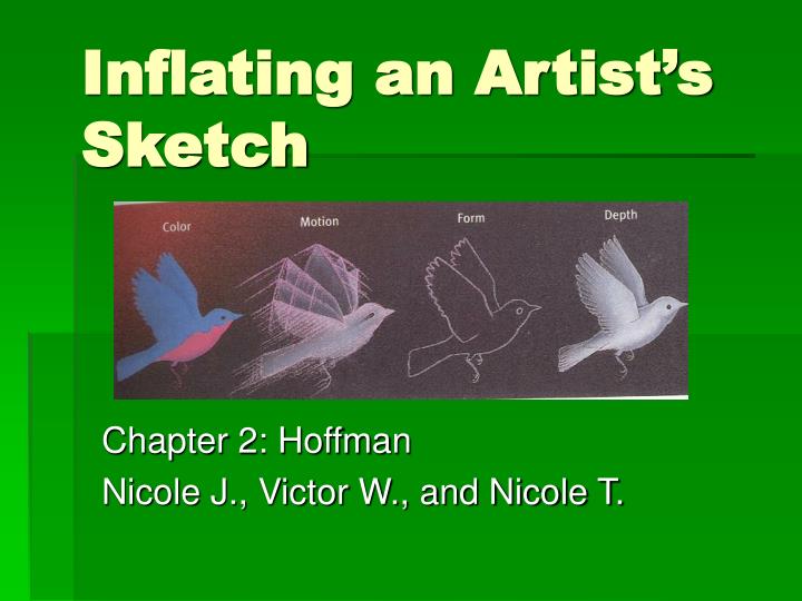
Inflating an Artist’s Sketch. Chapter 2: Hoffman Nicole J., Victor W., and Nicole T. Visual Processing Faults. How can the mind interpret objects incorrectly?. In this optic illusion line A appears to have more length than line B.

E N D
Inflating an Artist’s Sketch Chapter 2: Hoffman Nicole J., Victor W., and Nicole T.
Visual Processing Faults • How can the mind interpret objects incorrectly? In this optic illusion line A appears to have more length than line B. In this illusion, two parallel lines appear curved away from one another.
Everything you perceive visually is actually a construction of mental processes receiving sensory input. • Construction implies similar methods of visual interpretation – rules • Even these rules are fallible; sometimes one rule overrides another, sometimes they compromise, and often they deal with probabilities • The Fundamental Problem of Vision: An image at the eye has countless possible interpretations
The fundamental problem of seeing depth • The image at the eye has two dimensions; therefore it has countless interpretations in three dimensions • There is a principled ambiguity each time you need to see depth because of the construction of your 3D interpretation from the 2D image • However, individuals construct depth according to rules so the visual system is biased and will only construct worlds that conform to the visual rules Why is it easier to shape a 3D image from the Necker cube than either of the other cube viewpoints?
The fundamental role of visual rules • You construct visual worlds from ambiguous images in conformance to visual rules • These rules are implicit • Rather than violate the rules we will construct impossible 3D interpretations
Rule of generic views • Construct only those worlds for which the image is a stable view (i.e. generic) • Generic views vs. accidental views • The probability of an accidental viewpoint is very low – almost nothing Why does the “V” vertex make more visual sense than the “chopsticks” vertex on the right?
Rule 1 (generic views) • Always interpret a straight line in an image as a straight line in 3D • We see this Kopfermann figure as having straight lines in 2D therefore as having straight lines in 3D • This figure violates Rule 1 for generic visual representations • To see this figure as a cube we must rotate our view so that it is generic
Rule 2 (generic views) • If the tips of two lines coincide in an image, then always interpret them as coinciding in 3D • Example: If you alter the view slightly, a generic view is obtained and the cube is seen... Rules 1+2 predict this generic viewpoint and allow us to construct the cube.
Rules 3 (generic views) • Always interpret lines colinear in an image as colinear in 3D • The “attached boxes” violate the rule of generic views but are predicted by rule 4, the rule of proximity Even with our current restrictions by visual rules, this simple drawing can be interpreted in countless manners
Rule 4 (rule of proximity) • Interpret elements nearby in an image as nearby in 3D • Figure: The circles surrounding the Necker cube inherit their depth from the portion of the cube nearest to them
The rule of projection • Visual process by which three dimensions are smashed to two • Lead to the discovery of linear and natural perspectives in art • Supported by visual characteristics - sometimes vision can reveal depth where it is not present • Example – stereovision – 3D world is revealed in this image by crossing your eyes...
Rule 5 (projection) • Always interpret a curve that is smooth in an image as smooth in 3D
Surface Normals • Lines which indicate the local orientation of the surface of a 3D object rendered in 2D • Often used by geometers + vision researchers • foreshortening – normals w/ smaller angles have shorter projected lengths, normal parallel to your vision appears as a dot • Any line, including a normal line, has its longest projection when it is perpendicular to your line of sight • Examples – writing implement experiment
Rules 6 & 7 (projection) • Where possible, interpret a curve in an image as the rim of a surface in 3D • Where possible, interpret a T-junction in an image as a point where the full rim conceals itself: the cap conceals the stem
Principle directions and curvatures • Def. principle directions - Directions in which the surface curves most and least • These are always perpendicular to each other at every smooth point on any surface • Def. principle curvatures - Curvatures of the surface of an object corresponding to its principle directions • Def. silhouette – 3D image projected on 2D; the outline of the image is known as its bound, and a silhouette’s bound is projected by an object’s rim
Surfaces curve in three ways • Convex, concave, and saddle • Convex regions bound the material of objects • Concave regions bound pockets of air • Saddle regions provide a transition between convex and concave regions
Rules 8 & 9 (projection) • Interpret each convex point on a bound as a convex point on a rim • Interpret each concave point on a bound as a saddle point on a rim
Rule 10 • Construct surfaces in 3D that are as smooth as possible
Compared with human visual creative abilities, NASA’s IMP is a $6 million bucket of bolts…