Download

1 / 8
90 likes | 203 Views
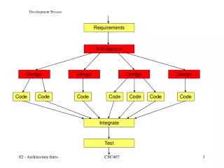
Development Process . Gear Box Housing -2 Part No.-7610610 . Ist operation –Boring Ø75N,Ø45,Grooving Ø51.2,X face milling,HoleØ11drilling , & M10Tapping on VMC. Adjust Rest. A. C1. A. A. A. Clamp. A. C2. Resting.

E N D
Development Process Gear Box Housing -2 Part No.-7610610
Ist operation –Boring Ø75N,Ø45,Grooving Ø51.2,X face milling,HoleØ11drilling , & M10Tapping on VMC Adjust Rest A C1 A A A Clamp A C2 Resting In this set-up due to clamping force of wedge clamp C1 & C2 the Flatness of Milling Face X goes above 0.1 for continuous ly , resolve this we have added pad to job for clamping & also clamp is added on fixture ( as shown in below slide for proper clamping of job)
Ist operation –Boring Ø75N,Ø45,Grooving Ø51.2,X face milling,HoleØ11drilling , & M10Tapping on VMC In this set-up due to clamping force of wedge clamp C1 & C2 the Flatness of Milling Face X goes above 0.1 for continuous ly, resolve this we have added pad to job for clamping & also clamp is added on fixture ( as shown in below slide for proper clamping of job)
Ist operation –Boring Ø75N,Ø45,Grooving Ø51.2,X face milling,HoleØ11drilling , & M10Tapping- Modified clamping D D Clamp Pad for Clamping Due to modified clamping Flattens observe from 0.033mm to 0.091mm.This pad is removed before next set up.
IInd operation –Boring Ø55 H8,Ø56,Grooving Ø58,K face milling,HoleØ8R8drilling , & M8 & M12 Tapping on VMC • In this set up due to dowel Hole 10R8 location concentricity of 75 N7 with respect to 55 H8 observed above 0.15 against 0.03. Location in Dowel 10 R8
IInd operation –Boring Ø55 H8,Ø56,Grooving Ø58,K face milling,HoleØ8R8drilling , & M8 & M12 Tapping on VMC by modified fixture. • In this set up due to location of boreØ75N7 concentricity of 75 N7 with respect to 55 H8 observed above 0.032 to 0.13 against 0.03.Due to this variation we have hold the setup & under investigation of causes for this variation. Clamp Location in Dowel 10 R8 & 75 N 7 bore
IIIrd operation –Boring Ø60 H8,face milling,HoleØ8 drilling , & M8 & M12 Tapping on HMC. • In this set up no problem for machining but we have found variation in measurement o f Sr. No . 87 Distance 95+/-0.2 & Sr. No. 459 Distance 98 +0.030
Gear Box Housing 7610610 machining set-ups. IInd Set - Up Ist Set - Up IIIrd Set - Up