Download
1 / 22
220 likes | 391 Views
SSWG May ’06: SAMS. Agenda. SAMS Hardware overview SAMS Software overview System status – performance to date Future work. Temperature span ( C). Relative Humidity (%). Alignment RMS tiptilt (a rc sec). Milestone 1. 3.2. < 66. 0.1. Milestone 2. 6.4. < 86. 0.1.

E N D
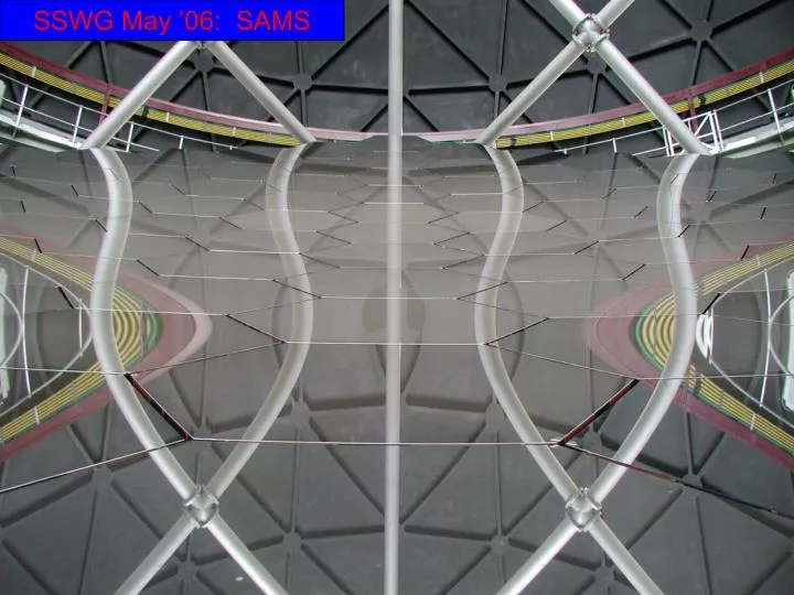
SSWG May ’06: SAMS SSWG Meeting 2006 May 8
Agenda • SAMS Hardware overview • SAMS Software overview • System status – performance to date • Future work SSWG Meeting 2006 May 8
Temperature span (C) Relative Humidity (%) Alignment RMS tiptilt (arcsec) Milestone 1 3.2 < 66 0.1 Milestone 2 6.4 < 86 0.1 Milestones for SAMS Historical records suggest this will require no realignment on 45% of nights and no more than 1 realignment per night for 70% of nights. This should cover ~75% of nights with no realignment necessary and 90% with no more than 1 realignment required. SSWG Meeting 2006 May 8
SAMS Hardware • Hardware reliability has been impeccable except for 1 manufacturing defect since installation ( numerical module has since been repaired) • 15 Sensors have burnt since commissioning the 4th and 5th rings of the array – represents a sensor failure rate of 3.1% • Burnt sensors are systematically replaced and drifting sensors are continually being investigated and fixed. • 96% of sensors work correctly, the balance consists of 9 burnt and 12 drifting sensors. • 2 segments have been coated and passed the capacitance test after coating. • 3 sensors did however fail shortly after being put back into service – damage may have been caused by improper handling, further investigation required
SAMS Software • The LabView portion of the system is stable and working reliably since the upgrade ( Oct 2005) • The upgraded rack software has solved all of the delay and spurious measurement issues ( jumps and severe offsets) • Phase 1 of the MACS sensor rejection software is complete • Future software development will focus on refining the sensor rejection software SSWG Meeting 2006 May 8
SAMS Software – Disabling drifting sensors • Sensor Drifting: Disable sensor to avoid growth of FoM • Possibleto disable wrong sensor. Need more sophisticated approach. • Working on it. SSWG Meeting 2006 May 8
Array Control • 91 segments, 273 actuators, 480 edge sensors • Capacitive edge sensors measure voltages related to gap (G) between • segments and relative height (H) of transmitter, receiver pairon adjacent edges • G = GPOL(VG) where VG = gap voltage • H = SPOL(G) * VH + OPOL(G) • GPOL, SPOL, OPOL are 3rd order polynomials • e.g., OPOL(G) = a3G3 + a2G2 +a1G +a0 • Sensor height – actuator position: • H = AS (A is a 480x273 matrix -> geometry) • Inverse problem: actuator positions from sensor heights: • S = (ATA )-1ATH • SAMS integrates for 4 minutes -> H ; S -> tip, tilt, piston • Rows corresponding to drifting, bad sensors removed from A matrix • 4 segments constrained in piston to control global tip,tilt,piston and GRoC • Figure of Merit (FOM): rms difference between observed, expected H • Error budget: 0.3asec(EE50) -> rms tiptilt ~0.1asec SSWG Meeting 2006 May 8
Mode Correction SSWG Meeting 2006 May 8
Mode Correction – Tried and rejected Corrected using last night’s coefficients Observed Corrected using same night’s coefficients SSWG Meeting 2006 May 8
Pseudo-heights • Allow for local non-uniformities in truss deformation with change of T • Hp = H + H ; H = G = (G – G0) (OPOL -> OPOL`) • S = (AT•A)-1ATHp SSWG Meeting 2006 May 8
Example Test: 2006-03-14 Rms Tip/Tilt as measured by CCAS – first iteration polynomials drift 0.28 arcsec/2.5°C SSWG Meeting 2006 May 8
2006-03-14 Pseudo-height polynomials (1) (from 2005 10 27) 0.14 arcsec/2.5°C SSWG Meeting 2006 May 8
2006-03-14 Pseudo-height polynomials, 2nd iteration (from 2006 03 14) 0.06 arcsec/2.5°C. Maximum rms TT ~ 0.1 arcsec. SSWG Meeting 2006 May 8
2006-03-13 Pseudo-height polynomials (1) and (2). <0.1arcsec/2°C. No hysteresis, but very little effect of revised polynomials – T gradients? SSWG Meeting 2006 May 8
2006-03-14 END SSWG Meeting 2006 May 8
2006-03-13 END SSWG Meeting 2006 May 8
Environmental Effects - Humidity • Reference sensors on Sital blocks in cage below primary • 3 different fixed gaps cover range in actual array, fixed heights SSWG Meeting 2006 May 8
SAMS Ongoing Investigations • FEM analysis of effect of T gradients • Real-time polynomial modification to include • environmental effects • Work session at Fogale (JWM(SAAO), BL and AC(Fogale)) • Refinement of polynomials per sensor • Incorporation of RH data • Investigate use of wavefront sensing SSWG Meeting 2006 May 8
END SSWG Meeting 2006 May 8
Other things? • modes, effect of sensor error on tt error • excess noise • effect of disabled sensors • mode correction à la JS SSWG Meeting 2006 May 8
Test procedure • Align primary; rms Tiptilt ~0.06 arcsec • Zero SAMS • Control segments with SAMS in closed loop • Observe primary with CCAS; record tip, tilt, piston • Remove global Tip/Tilt, GRoC from SAMS data • Estimate true piston by least-squares • Compute SAMS height errors SSWG Meeting 2006 May 8