Download
1 / 36
360 likes | 367 Views
Design of a Tensile Load Frame for a Scanning Electron Microscope Senior Design Project 04004. Project Manager - Robert Rinefierd Faculty Mentor - Dr. Elizabeth Debartolo. Team Members. Project Manager – Robert Rinefierd Lead Engineer – Evan Kastner Mechanical Engineers

E N D
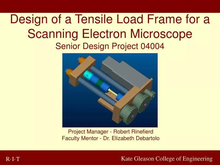
Design of a Tensile Load Frame for a Scanning Electron Microscope Senior Design Project 04004 Project Manager - Robert Rinefierd Faculty Mentor - Dr. Elizabeth Debartolo Kate Gleason College of Engineering
Team Members • Project Manager – Robert Rinefierd • Lead Engineer – Evan Kastner • Mechanical Engineers • Nicholas Currier, Evan Kastner, Robert Rinefierd, Blaine Stuart • Industrial Engineer • Kennedy Mogwai • Computer Engineer • Evan Brunner Kate Gleason College of Engineering
Agenda • Introduction • Concept Development • Feasibility Assessment • Objectives and Specifications • Design Analysis • Preliminary Design • Production Schedule Kate Gleason College of Engineering
Project Overview • Design and construct a load frame to apply tensile loads to specimens inside the Scanning Electron Microscope (SEM) in the CIMS Materials Science Lab • The load frame should be lightweight, modular, and easy to carry between buildings • Developed for Mechanical Engineering Department faculty and students performing metallographic research • Funded by the Mechanical Engineering department Kate Gleason College of Engineering
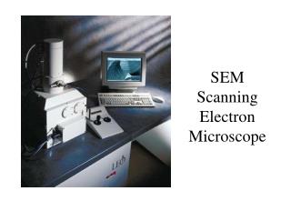
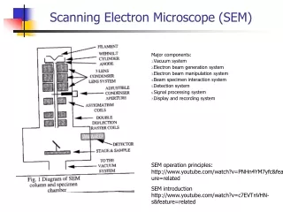
What is a Scanning Electron Microscope? • High powered microscope for analysis of surfaces or near-surface areas (up to 25,000X) • Has a good depth of field, so images remain in focus • Good tool for evaluating fracture surfaces • Capable of producing chemical analysis of surfaces Kate Gleason College of Engineering
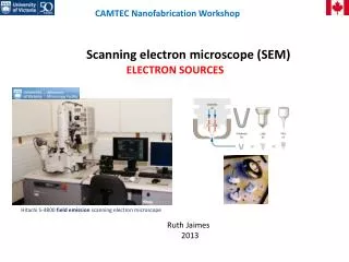
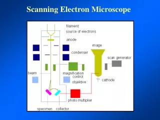
How does it work? • Electrons from an electron gun are reflected off of the surface • Image is produced from the energy and electrons reflected by the surface • Image is displayed on a monitor screen • Magnification controlled by reducing the scanned area Electron Microscopy and Analysis, Goodhew, 1992 Kate Gleason College of Engineering
The Position Fixture Available space is roughly 9”wide, 3” high, and 11” deep. Doors and ports can be replaced to allow for tensile controls or a window to monitor tensile display on frame. Dials control motors to adjust the position. The frame has xyz and tilt controls. Kate Gleason College of Engineering
Design Constraints • Spatial constraints • Vacuum compatibility • CIMS Materials Lab owns the SEM; Mechanical Engineering department will own the load frame • Load frame to mount to existing position fixture • Limited to existing ports for vacuum feedthrough • Budget Kate Gleason College of Engineering
Concept 1 – Internal Motor, 2 Screws • Internal components • 2 power screws • Motor driven • Advantages: reliable • Disadvantages: slightly over budget limit Kate Gleason College of Engineering
Concept 2 – Internal Motor, 1 Screw • Motor • Stepper motor • Drive Train • Single screw • Mounting Frame • Fixed base • Grips • Self locking • Interface • Vacuum • Control/ Display • Automatic • Closed loop Kate Gleason College of Engineering
Concept 3 – Manually Powered • Uses a removable hand-driven crank to apply load • Advantages: • Cheap • Reliable • Easily within scope of team’s knowledge • Disadvantages: • Down time to change loads • Eliminates ability to analyze load dynamically Kate Gleason College of Engineering
Concept 4 – External Motor • Advantages • additional internal space • air cooled heat dissipation • Disadvantages • complex gearing • lack of mobility • cost Kate Gleason College of Engineering
Feasibility Assessment • Introduction • Major part of design activity • Decision making activity • Qualitative or quantitative • Attributes • Resources • Economical • Schedule • Technical feasibility Kate Gleason College of Engineering
Feasibility Assessment • Evaluation of Design Concepts • Pugh Evaluation • Similar to “paired comparison” • Qualitative evaluation • Reference concept • Eliminate weak concepts • Weighted Concept Evaluation • Systematic quantitative • Performed in Six step • Relative weight importance • Value judgment Kate Gleason College of Engineering
Objectives and Specifications • Performance • 200 lbs Compression, 1000 lbs Tension (2000 lbs Target) • Position and Load Control • Live Displays • Implementation • Cylindrical Threaded Specimen • Remove Part of Position Frame • Evaluation • Pass Fatigue and Stress Calculations • Safety • Vacuum • Grounding Kate Gleason College of Engineering
Motor and Gearbox Selection • Determining Factors in Motor Selection: • Vacuum Rating – Vapor Pressure • Space Constraints • Cost • Determining Factors in Gearbox Selection: • Those Listed Above + • Reduction Ratio • Continuous Output Torque Ceiling Kate Gleason College of Engineering
Advantages of Design • Overall Reduction Offers Near Continuous Resolution From a Stepper Motor • Impossible for Motor To Damage Gearbox • Largest Output Torque Possible with Size Constraint • Large Torque Produced to Handle Dry Friction Problem Likely to Create a Large Factor of Safety Kate Gleason College of Engineering
Vacuum Compliance • Obstacles With Vacuum Compliance • Cost • Time Budget • Investigation of Component Materials • Cleansing of Machined Parts & Pretreatments • Rare Properties (Friction Coefficients) • Lack of Substitutes (Scarcity Price) • Heat Dissipation (No Convection Medium) Kate Gleason College of Engineering
Vacuum Compliance • 300 Series Stainless Steel When Possible • High Corrosion Resistance • Outgassing Unproblematic • All Materials of All Non-Vacuum Rated Components Evaluated or Will Be Evaluated For Vacuum Compatibility Kate Gleason College of Engineering
Power screws • ACME ¾-10 - Self Locking Capability • COTS Product: Nook Industries, Keystone • Exact tooth geometry unknown (pitch angle) • Bronze nut rated to 9000lbf force and 2250lbf dynamic force • Bronze nut must be replaced with stainless steel nut (cost under investigation) • Likelihood of need for custom flange mount for stainless steel replacement nut Kate Gleason College of Engineering
Gear linkage • Consists of two 2 ½ inch diameter gears and one 1 inch diameter gear. • All gears are connected inline. • Achieves a final gearing reduction of 2 ½. • 1 inch diameter gear attached to shaft of gearbox. • Drives one 2 ½ inch diameter gear which drives the other. • 2 ½ diameter gears drive the two power screws. Kate Gleason College of Engineering
Gear Specifications • Gears are to be purchased • Custom Manufacture • Type: Cylindrical • Pitch: 16 • Face Width: 0.75 inch • Material: 8620 Case Hardened Steel or 17-4 (0.2% Yield 200KSI) • 20° pressure angle Kate Gleason College of Engineering
Stress Analysis • Key Design Issue: Transfer of a Torque To Create a Linear Force • Concepts Investigated • Interference Pin Connection • Generation of clamping force with shoulder screw – using friction to transfer torque • Steel on steel bearing contact surface • Needle bearing with cap to secure axial load; stepped ACME shaft with keyway • Lowers torque dramatically Kate Gleason College of Engineering
Needle Bearing Option • Shoulder screw option requires frequent lubrication to avoid metal transfer • Vacuum lubricant: $300/oz, 10-6 torr vacuum • Bearing allows continuation of ACME shaft to transfer lesser torque while withstanding high radial load from cylindrical gears • Details in flux due to late discovery of affordable vacuum compatible bearings Kate Gleason College of Engineering
Grip Design • 1 inch diameter cylinder 1 inch long • 3/8 – 24 female threads bored through center • Material: 303 Stainless Steel • Knurling around surface • Reduces stress concentrations • Improves grip ability • Added Bonus: Also functions as a fastener within tensile stage. Kate Gleason College of Engineering
Test Specimens • Round “dog-bone” shape • Both ends of specimen cut to 3/8 – 24 male threads • Screw into female threads of grips • Viewable Area • Gage length of 1 inch • Diameter of ¼ inch Kate Gleason College of Engineering
Mounting to Position Fixture • Purpose • Interface between stage and SEM • Mounting surface for stage • Hold SEM position resolution device • How? • Match bolt holes • Calculate stresses in mating screws from base to the rest of load frame in worst case scenario Kate Gleason College of Engineering
Controls • Control through LabView • End user definable • Serial port link • Stock or freeware libraries • Hard emergency stop Kate Gleason College of Engineering
Control Software • User defines boundaries of operation previous to entry into chamber • Interrupt driven communication between user interface and MCU Kate Gleason College of Engineering
Vacuum Interface Vacuum chamber Available port on the chamber door - 2 ¾ “ Flange - Tight seals around all electrical connections and plates Controls and digital monitor may be located outside the chamber Kate Gleason College of Engineering
Vacuum Chamber Feed through • What is needed • 8 wires through chamber wall • 4 for stepper • 2 for thermocouple • 2 for load cell • Places looked • Nor Cal (www.n-c.com) • MDC (www.mdc-vacuum.com) • Varian Inc (www.varian-inc.com) • Veeco (www.veeco.com) Kate Gleason College of Engineering
Test Plan • New scientific function – that of test and evaluation engineering • Autonomous activity – product development cycle • Integrated Test plan • Objectives & requirement • Detailed test plan & procedure • Test report requirement • Project scheduling • SEM Integrated Test Plan – Development Test & Evaluation • Components or Parts Testing • Subassemblies Testing • Deployment Testing Kate Gleason College of Engineering
Production Schedule • February: • Submit purchase order for motor, gearbox, vacuum lubricant, load cell, electrical feedthrough and components, and steel • Mid-March: • Completion of all aspects of mechanical design • Submit order for all remaining components • Completion of detailed design including FEA analysis • Design for assembly analysis • April: • Hand fabrication of steel components • Integration of control system • May: • Testing and troubleshooting Kate Gleason College of Engineering
Cost Estimate Kate Gleason College of Engineering
Questions and Discussion Kate Gleason College of Engineering