Download
1 / 5
50 likes | 173 Views
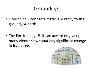
Grounding: electrical modelling; proposal for progressing. Status of emgn modelling reviewed at CCIC-01

E N D
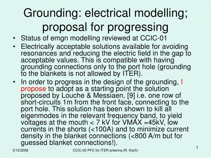
Grounding: electrical modelling; proposal for progressing • Status of emgn modelling reviewed at CCIC-01 • Electrically acceptable solutions available for avoiding resonances and reducing the electric field in the gap to acceptable values. This is compatible with having grounding connections only to the port hole (grounding to the blankets is not allowed by ITER). • In order to progress in the design of the grounding, I propose to adopt as a starting point the solution proposed by Louche & Messiaen, [9] i.e. one row of short-circuits 1m from the front face, connecting to the port hole. This solution has been shown to kill all eigenmodes in the relevant frequency band, to yield voltages at the mouth < 7 kV for VMAX =45kV, low currents in the shorts (<100A) and to minimize current density in the blanket connections (<800 A/m but for guessed blanket connections!). CCIC-03 PFC for ITER antenna (R. Koch)
The following points should be addressed: • If the blanket modules are not the solid blocks used in the electromagnetic modelling; if the blanket modules are connected differently from what was assumed, electromagnetic computations have to be re-run. • The feasibility of using bellows for the grounding elements has to be investigated • The compatibility of the grounding solution with disruption currents and forces has to be assessed (Does ITER have the tools and manpower to check this?) • The row of grounding cylinders could be replaced by continuous grounding bars • If there are signs of strong eigenmode excitation in the harmonics range the positioning of additional grounding points can be investigated • The RF dissipation in the short-circuits should be computed. CCIC-03 PFC for ITER antenna (R. Koch)
Before adopting an electrical grounding solution, we also need to sort out whether the presence of the gap at the blanket level is going to worsen the situation with respect to parallel electric fields (TOPICA and/or MWS) as compared to earlier TOPICA simulations without gap. According to recent TOPICA computations [6] “The effect varying the grounding position is small and depends on the phasing”. • Note however that in [9], the presence of the short-circuits is seen to affect both antenna impedance and plug voltage at certain frequencies CCIC-03 PFC for ITER antenna (R. Koch)
Questions • Do we agree to start with one row (or one bar) of short-circuits 1m from the front face? • Base optimization on this assumption? • Optimization: which direction? CCIC-03 PFC for ITER antenna (R. Koch)
Heat loads on plasma facing component • The responsibilities for further developing the front-face components of the antenna are unclear (to me). Is CEA responsible for this activity? • Mechanical resistance of the Faraday shield and antenna frame limiters to disruptions remain to be evaluated. • If the antenna must be able to take additional loads from sheath effects with peaks of several MW/m2, its front facing components have to be redesigned. Revised thermal modelling is required. • Frame limiters of the antenna may have to be redesigned because of the new configuration of the first wall around port holes. • Heat loads on surrounding blanket modules may be strongly increased dur to RF sheaths CCIC-03 PFC for ITER antenna (R. Koch)