Download
1 / 69
690 likes | 809 Views
Photon colliders. Valery Telnov Budker INP, Novosibirsk Lepton collider workshop, MIT, US, April 10, 2013. Contents. Inroduction ILC CLIC SAPPHIRE and others Super γγ factory Conclusion. GKST 1981. b~ γσ z ~ 1 mm. α c ~ 25 mrad. ω max ~0.8 E 0 W γγ , max ~ 0.8·2E 0

E N D
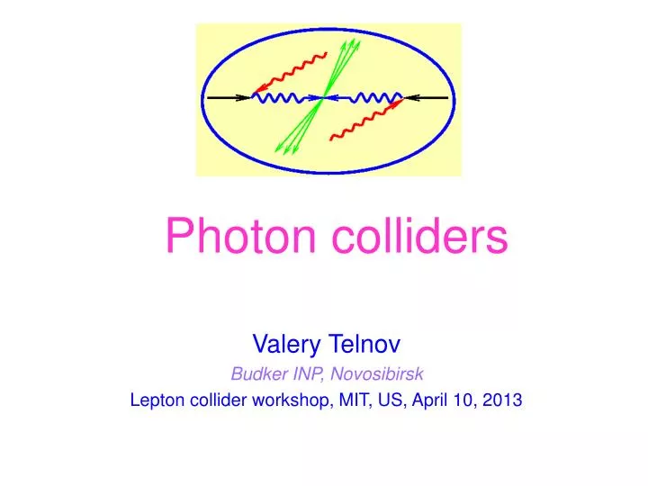
Photon colliders Valery Telnov Budker INP, Novosibirsk Lepton collider workshop, MIT, US, April 10, 2013
Contents • Inroduction • ILC • CLIC • SAPPHIRE and others • Super γγ factory • Conclusion Valery Telnov
GKST 1981 b~γσz~1 mm αc~25 mrad ωmax~0.8 E0 Wγγ, max ~ 0.8·2E0 Wγe, max ~ 0.9·2E0 Valery Telnov
The electron polarization increases the number of high energy photons nearly by factor of 2). Valery Telnov
Ideal luminosity distributions, monohromatization (ae is the radius of the electron beam at the IP, b is the CP-IP distance) Electron polarization increases the γγluminosity in the high energy peak up to a factor of ~3-4 (at large x). Valery Telnov
Highest energy scattered photons are polarized even at λe=0 (see (b)) The electron polarization makes the region with a high polarization at ω~ωm) wider (compare a and b). Valery Telnov
Linear polarization of photons σ 1 ± lγ1lγ2 cos 2φ± for CP=±1 Linear polarization helps to separate H and A Higgs bosons Valery Telnov
ξ2≤0.2-0.3 is required Valery Telnov
Realistic luminosity spectra ( and e)(with account multiple Compton scattering, beamstrahlung photons and beam-beam collision effects) (decomposed in two states of Jz) (ILC) Usually a luminosity at the photon collider is defined as the luminosity in the high energy peak, z>0.8zm. For ILC conditions Lγγ(z>0.8zm) ~0.1 Le+e-(nom) (but cross sections in γγ are larger by one order!) Valery Telnov
Physics at PLC Physics at PLC was discussed so many times (>1000 papers) that it is difficult to add something essential. Most of examples are connected with production of the Higgs bosons or SUSY particles. At present only light Higgs boson is discover. Below I will just remind some gold-plated processes for PLC and model independent features. Valery Telnov
Some examples of physics at PLC realistic simulation P.Niezurawski et al γ (is considered for PLC since 1980th) γ V.Telnov,1999 ~5 (previous analyses) ILC For MH=115-250 GeV At nominal luminosities the number of Higgs in γγ will be similar to that in e+e- S.Soldner-Rembold (thr first simulation) Valery Telnov
unpolarized beams So, typical cross sections for charged pair production in γγ collisions is larger than in e+e- by one order of magnitude Valery Telnov
Supersymmetry in For some SUSY parameters H,A can be seen only in γγ (but not in e+e- and LHC) Valery Telnov
W ' γ γ e e Supersymmetry in e ~ e ~ e W ' χ1 ν Valery Telnov
Physics motivation for PLC(independent on physics scenario)(shortly) In , e collisions compared to e+e- • the energy is smaller only by 10-20% • the number of events is similar or even higher • access to higher particle masses (H,A in γγ, charged and light neutral SUSY in γe) • higher precision for some phenomena • different type of reactions (different dependence on theoretical parameters) It is the unique case when the same collider allows to study new physics in several types of collisions at the cost of rather small additional investments Valery Telnov
Remark on Photon collider Higgs factories Photon collider is attractive for measurement of Br(H→bb)Г(H→γγ), but can not measure, Br(bb, cc, gg, ττ, μμ, invisible), therefore PLC is the best in combination with e+e-, parallel work or second stage. There were suggestions (H. Sugawara, 2009) to built a PLC Higgs factory as the ILC precursor, but it was not accepted by physics community mainly because e+e- physics case (for Higgs study) is stronger Valery Telnov
Photon collider at ILC Valery Telnov
The photon collider at ILC (TESLA) has been developed in detail at conceptual level, all simulated, all reported and published (TESLA TDR (2001), etc. The conversion region: optimization of conversion, laser scheme. The interaction region: luminosity spectra and their measure-ment, optimization of luminosity, stabilization of collisions, removal of disrupted beams, crossing angle, beam dump, backgrounds. The laser scheme (optical cavity) was considered by experts, there is no stoppers. Required laser technique is developed independently for many other applications based on Compton scattering. Recently LLNL started work on LIFE lasers for thermonuclear plant which seems very attractive (one pass laser). Further developments need political decisions and finances. Valery Telnov
b~γσz~1 mm αc~25 mrad ωmax~0.8 E0 Wγγ, max ~ 0.8·2E0 Wγe, max ~ 0.9·2E0 Valery Telnov
Realistic luminosity spectra ( and e)(with account multiple Compton scattering, beamstrahlung photons and beam-beam collision effects) (decomposed in two states of Jz) (ILC) Usually a luminosity at the photon collider is defined as the luminosity in the high energy peak, z>0.8zm. For ILC conditions Lγγ(z>0.8zm) ~ 0.1Lee ~0.15Le+e- (but cross sections in γγ are larger by one order!) For γe it is better to convert only one electron beam, in this case it will be easier to identify γe reactions, to measure its luminosity (and polarization) and the γeluminosity will be larger. Valery Telnov
Properties of the beams after CP,IP Electrons: Emin~6 GeV, θx max~8 mrad θymax~10 mrad practically same for E0=100 and 250 GeV For low energy particles the deflection in the field of opposing beam An additional vertical deflection, about ±4 mrad, adds the detector field αc= (5/400) (quad) + 12.5 ·10-3(beam) ~ 25 mrad Valery Telnov
Disrupted beam with account of the detector field (at the front of the first quad, L~4 m) Ee, min~6 GeV 2E0=200 GeV 2E0=500 GeV With account of tails the save beam sizes are larger by about 20 %. Valery Telnov
Requirements for laser • Wavelength ~1 μm (good for 2E<0.8 TeV) • Time structure Δct~100 m, 3000 bunch/train, 5 Hz • Flash energy ~5-10 J • Pulse length ~1-2 ps If a laser pulse is used only once, the average required power is P~150 kW and the power inside one train is 30 MW! Fortunately, only 10-9 part of the laser photons is knocked out in one collision with the electron beam, therefore the laser bunch can be used many times. The best is the scheme with accumulation of very powerful laser bunch is an external optical cavity. The pulse structure at ILC (3000 bunches in the train with inter-pulse distance ~100 m) is very good for such cavity. It allows to decrease the laser power by a factor of 100-300. Valery Telnov
Laser system The cavity includes adaptive mirrors and diagnostics. Optimum angular divergence of the laser beam is ±30 mrad, A≈9 J (k=1), σt ≈ 1.3 ps, σx,L~7 μm Valery Telnov
Nonlinear effects in CS are important for optimization The figure shows how the conversion efficiency depends on the f# of the laser focusing system for flat top beams in radial and Gaussian in the longitudinal directions The parameter T.V. characterizes the probability of Compton scattering on several laser photons simultaneously, it should be kept below 0.2-0.4, depending on the par. x) For ILC beams, αc=25 mrad, and θmin=17 mrad (see fig. with the quad) the optimum f# =f/2a ≈ 17, A≈9 J (k=1), σt ≈ 1.3 ps, σx,L~7 μm. So, the angle of the laser beam is ±1/2f# = ±30 mrad, The diameter of the focusing mirror at L=15 m from the IP is about 90 cm. f- focal distance a – mirror radius Valery Telnov
Layout of the quad, electron and laser beamsat the distance 4 m from the interaction point (IP) Valery Telnov
Recently new option has appeared, one pass laser system, based on new laser ignition thermonuclear facility Project LIFE, LNNL 16 Hz, 8.125 kJ/pulse, 130 kW aver. power (the pulse can be splited to the ILC train) Valery Telnov
Laser diodes cost go down at mass production, that makes one pass laser system for PLC at ILC and CLIC realistic! Valery Telnov
Dependence of the γγ luminosity on the energydue to laser parameters V.Telnov, LCWS04, physics/0411252 1- k=0.64 at 2E=500, A = const, ξ2 = const, λ = 1.05 μm 2- k=0.64 at all energies, ξ2 A, λ =1.05 μm 3- k=0.64 at all energies, ξ2 A, λ =1.47 μm (to avoid pair creation) Laser system with λ~1.06μm is suitable for 2E=200-700 GeV Valery Telnov
Factors limiting γγ,γe luminosities ILC 300 At e+e-the luminosity is limitted by collision effects (beamstrahlung, instability), while in γγ collsions only by available beam sizes or geometric e-e- luminosity (for at 2E0<1 TeV). Valery Telnov
Photon collider at CLIC Valery Telnov
CLIC main parameters Valery Telnov
Comparison of ILC and CLIC parameters (important for PLC) Laser wave length λ E for ILC(250-500) λ~1μm, for CLIC(250-3000) λ~ 1 - 4.5 μm Disruption angle θd~(N/σzEmin)1/2 For CLIC angles θdislarger on 20%, not important difference. Laser flash energy A~10 J for ILC, A~5J for CLIC Duration of laser pulseτ~1.5ps for ILC, τ~1.5 psfor CLIC Pulse structure ILC Δct~100 m, 3000 bunch/train, 5 Hz(fcol~15 kH) CLIC Δct~0.15 m, ~300 bunch/train, 50 Hz(fcol~15 kH) Laser system ILC – a ring optical cavity with Q>100 CLIC –one pass system (or short linear cavity?) Valery Telnov
Laser system for CLIC Requirements to a laser system for a photon collider at CLIC Laser wavelength ~ 1 μm Flash energy A~5 J Number of bunches in one train 354 Length of the train 177 ns=53 m Distance between bunches 0.5 nc Repetition rate 50 Hz The train is too short for the optical cavity, so one pass laser should be used. The average power of one laser is 90 kW (two lasers 180 kW). Valery Telnov
Possible approaches to CLIC laser system • FELs based on CLIC drive beams. • There were suggestions to use CLIC drive beams to generate light flashes (FEL), but they have not enough energy to produce the required flashes energy. In addition, the laser pulse should be several times shorter than the CLIC drive bunch. • For any FEL, the laser power inside 177 ns train should be about 20 GW! While the average power 200 kW. The problem is due to very non uniform pulse structure. Valery Telnov
Solid state lasers pumped by diodes. One can use solid state lasers pumped by diodes. There are laser media with a storage time of about 1 ms. One laser train contains the energy about 5x534=2000 J. Efficiency of the diode pumping about 20%, therefore the total power of diodes should be P~2*2000/0.001/0.20~20 MW. LLNL system LIFE based on diode pumping, page 27, is very close to CLIC requirements and can be reconfigured for CLIC (and ILC) (talk at HF2012, see Gronberg’s at this meeting) diodes amplifire Valery Telnov
Another suggestion (Telnov,2010): to use FELs with the energy recuperation instead of diodes for pumping the solid state laser medium. The electron beam energy can be recuperated using SC linac. Only 3% of energy is lost to photons and not recuperated. With recuperation and 10% wall plug RF efficiency the total power consumption of the electron accelerator from the plug will be about 200 kW/ 0.1 = 2 MW only. The rest past of the laser system is the same as with solid state lasers with diode pumping. The FEL pumped solid state laser with recuperation of electron beam energy is very attractive approach for short train linear colliders, such as CLIC. Valery Telnov
Storage of the pumping energy inside solid-state laser materials reduces the required FEL power inside the CLIC train by a factor 1 ms/ 177 ns=5600! Such FEL can be built already now. Valery Telnov
Luminosity Usually a luminosity at the photon collider is defined as the luminosity in the high energy peak, z>0.8zm. At energies 2E<1 TeV there no collision effects in γγcollisions and luminosity is just proportional to the geometric e-e- luminosity, which can be, in principle, higher than e+e- luminosity. Lγγ(z>0.8zm) ~0.1L(e-e-,geom) (this is not valid for multi-TeV colliders with short beams(CLIC) due to coherent e+e- creation) For CLIC(500) Lγγ(z>0.8zm) ~ 3·1033for beams from DR Valery Telnov
Luminosity spectra for CLIC(3000) Here the γγluminosity is limitted by coherent pair creation (the photon is converted to e+e- pair in the field of the opposing beam). The horizontal beam size can be only 2 times smaller than in e+e- collisions. Lγγ(z>0.8zm) ~8·1033 Valery Telnov
Photon collider Higgs factory SAPPHiRE Valery Telnov
Aug. 2012 Valery Telnov
The scheme is based on LHeC electron ring, but shorter beams (σz = 30μm) ) and somewhat higher energy, 80 GeV Valery Telnov
200 kHz!!! !!! ! Valery Telnov
Main critical remarks on SAPPHIRE • The emittance dilution in arcs is too optimistic, compared to LHeC it was suggested to decrease the dipole section length by a factor of 4 and thus to decrease the dilution by a factor of 64! However, in this case the quads gradient should be 42=16 times larger! (May be OK?) • The initial beam normalized emittances, 5 and 0.5 mm mrad in X and Y directions corresponds to best emittances of unpolarized RF guns. PLC needs polarized electrons. Present polarized DC guns (polarized RF guns do not exist yet) have emittances > 20 times larger! It means that the luminosity will be 20 times smaller. That is why PLC at ILC assumes D However, F.Zimmernann collected information from several centers that low emittance polarized RF guns makes good progress and will appear soon. That would be great for any PLC! • Conservation of polarization in rings is a problem (due to the energy spread). • The bunch length (σz = 30 μm) is very close to condition of coherent radiation in arcs. Valery Telnov
4. The length of the ring 9 km (2.2 km linac, 30 km arcs). The LC with G=30 MeV/m would have L=6 km total length (with the final focus) and can work with smaller emittances and thus can have a higher luminosity. Where is profit? 5. The PLC with E=80 GeV and λ=1.06/3 μm have very low energy final electrons with energies down to E=2 GeV. Besides the electron bunch length is very short. This courses very large disruption angles (θ~1/(Eσz)1/2 in the field of opposing beam and due to deflection in the solenoid field (due to crab crossing). It makes unacceptable background situation and increase minimum angle for laser optics. Namely due to this reason TESLA (ILC) always considered the Higgs factory with E>100 GeV and λ=1.06/3 μm. Higgs factory with λ=1.06/2μmis may be possible, but this requires higher Sapphire energy, which is not possible due do to unacceptable emittance dilution and energy spread. Valery Telnov
6. Ring colliders (Sapphire) have no possibility for increasing energy. 7. The repetition rate 200000 is very uncomfortable for laser system, optical cavity can help, but it is much more demanded than for ILC. 7. It is obvious that e+e- is better for the Higgs study, there is no chance to get support of physics community, if this collider is instead of e+e-(worse that precursor). Valery Telnov
option: self-generated FEL g beams (instead of laser)? (I do not believe, there is no space near IP!) e- (80 GeV) wiggler converting some e- energy into photons (l≈350 nm) e- (80 GeV) e-bend optical cavity mirrors e- bend Compton conversion point gg IP “intracavity powers at MW levels are perfectly reasonable” – D. Douglas, 23 August 2012 example: lu=200 cm, B=0.625 T, Lu=100 m, U0,SR=0.16 GeV, 0.1%Pbeam≈25 kW scheme developed with Z. Huang Valery Telnov
Below are several examples of Sapphire followers, stimulated by the need of some Higgs factory. Valery Telnov
SAPPHiRE “fits” on the SLAC site Valery Telnov