Download
1 / 25
250 likes | 373 Views
CMS EMU CSC Upgrade Digital CFEB. Ben Bylsma The Ohio State University. Overall View of Data Acquisition System. Cathode Front End Board (CFEB). Input/Output. Optimized for Precision Position Measurement. 5 cfebs/chamber, 96 strips/cfeb 96 switch capacitors/strip

E N D
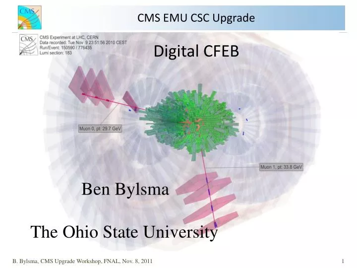
CMS EMU CSC UpgradeDigital CFEB Ben Bylsma The Ohio State University B. Bylsma, CMS Upgrade Workshop, FNAL, Nov. 8, 2011
Overall View of DataAcquisition System B. Bylsma, CMS Upgrade Workshop, FNAL, Nov. 8, 2011
Cathode Front End Board (CFEB) Input/Output Optimized for Precision Position Measurement • 5 cfebs/chamber, 96 strips/cfeb • 96 switch capacitors/strip • system is self triggering BUCKEYE (ASIC) - amplifies and shapes input pulse SCA (ASIC) - analog storage for 20 MHz sampled input pulse ADC - events with LVL1ACC digitized and sent to DAQ Motherboard (25 nsec/word) Comparator ASIC - generates trigger hit primitives from shaped pulse Controller FPGA - controls SCA storage and digitization B. Bylsma, CMS Upgrade Workshop, FNAL, Nov. 8, 2011
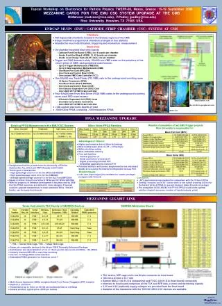
LHC CSC Trigger Rates - ME1/1 most important chamber for PT Resolution - Also the Highest Background rates for n’s and ’s L1 Accept: 100 kHz LCT rate: 69 kHz per CFEB (worst case – ME1/1) Estimated LCT rate for 10**34 lumi (D. Acosta et al, 2001) Chamber Type LCT rate per CFEB (kHz) ME1/1 69 ME1/2 4 ME1/3 2 ME2/1 21 ME2/2 3 ME3/1 11 ME3/2 2 ME4/1 8 ME4/2 9 (Recent measurements of singles background consistent with these rates) L1-LCT coincidence rate per CFEB: 100 kHz x 70 kHz x 75 ns = 0.5 kH Digitization time (with 6 ADCs on each CFEB) 16 channels x 16 samples/channel x 100 ns = 26 ms B. Bylsma, CMS Upgrade Workshop, FNAL, Nov. 8, 2011
Data Bottlenecks in CSC DAQ at SLHC • CFEB’s 96 Capacitors/channel is main DAQ rate limiter • Capacitor Storage Arranged in 12 blocks of 8 capacitors Simple Model CFEB Capacitor Storage Transfer to DMB Complete Beam Crossing LCT L1A·LCT 0.8sec 2.4sec 26sec 16 Cap Delay Cap Storage (Poisson) Cap Digization (Queue) Caps can be used for storage when all others in use For SLHC this is the main capacitor usage B. Bylsma, CMS Upgrade Workshop, FNAL, Nov. 8, 2011
ME1/1 Effective SCA Buffer Occupancy at SLHC We Expect ME1/1 CFEB SCA’s to Overflow • At SLHC: use same L1 accept rate assuming rates go up linearly. Maximum LCT rate is 700 kHz (ME1/1), L1-LCT match rate is 5.25 kHz. • Average number of LCTs during 5.2 ms (=6ms-0.8ms) holding time for 2-blocks: h=5.2x10-6x700x103=3.64 • Average number of L1-LCT matches during 26 ms digitization time: r=26x10-6x5.25x103=0.1365 • Probability of overuse of SCA: 0.09 !!!!!!!!! B. Bylsma, CMS Upgrade Workshop, FNAL, Nov. 8, 2011
Digital CFEB – A Nice Idea for the SLHC Replace SCA storage and Conventional ADC and withFlash ADC and Digital Storage Serial LVDS 8 pairs CFEB ref SCA ADC ADC ADC FPGA FPGA To DMB over Skewclear + + + pre 16 8 8 16 12 bits pre To DMB over Fiber 16 pairs Chan-link - - - ref mux Pipeline/FIFOs 21 bits Serial GTX Opt. Trnscvr 8 pairs ~3.2Gbps ref 21:3 280 Mbps . . . . . . . . . 6 layers Digitization Latency Readout Digitization and Readout Analog storage Analog storage - no coincidence DCFEB Pipeline FIFO Analog storage with L1A*LCT coincidence event xfer LCT L1A 3.2 to 6.4µS L1A ~3.2µS 8.2 to 11.4µS Release Caps ~26µS event LCT • No Deadtime • No rate worries • No need for LCT • Simpler Firmware B. Bylsma, CMS Upgrade Workshop, FNAL, Nov. 8, 2011
A Problem with ME1/1 Triggering CSC Trigger disastrous for >2.1 - for rate split strips in half - for $$$ ganged strips (48 strips modulo 16) - attempts to fix in firmware lead to rate problem B. Bylsma, CMS Upgrade Workshop, FNAL, Nov. 8, 2011
ME4/2 Linked to ME1/1 Upgrade • New ME4/2 chambers need boards. • Propose 514 new cards ME1/1 • Old cards to populate ME4/2 Upgrade • ME1/1 Obvious for First Upgrade • Handles highest particle flux • Most important for momentum • resolution. • Removes ganged strips in ME1/1a DCFEBs were designed for high Luminosity. B. Bylsma, CMS Upgrade Workshop, FNAL, Nov. 8, 2011
Improve Board-Board Communication Present CFEB-Trigger CFEB-DMB/TMB Communications 2 50-pin Skew-Clear Cables per CFEB Channel Links 280 Mb/s ME1/1 Cable Max Spec Length (a few problems) DMB/TMB boards need 7 (Skew –Clear won’t fit) Special Manufacturing … Preferred Option Replace Skew-Clear Cables with Optical Fiber (Snap-12) Room for 7 CFEBs on DMB/TMB More Reliable COTs Cheaper than copper B. Bylsma, CMS Upgrade Workshop, FNAL, Nov. 8, 2011
DCFEB R&D Prototype • Prototype to Test Buckeye Amplifier Connection to FLASH ADCs - use most of old CFEB layout , input protection, noise isolation, trigger path - use old CFEBs Pcrate communications - 4 differential amp options - realistic Virtex-6 digital pipeline - fiber optical output for tests • Two cards received in mid-March - Fab: Compunetics, 20 layer board, special dielectric(Dk=3.5) to reduce thickness with same trace impedance • assembly: Dynalab • Bench Testing • OSU test station, Pcrate • CERN building 904 We can bypass 2nd Prototype and go to Preproduction Board B. Bylsma, CMS Upgrade Workshop, FNAL, Nov. 8, 2011
Buckeye 5-pole plus 1-pole 1-zero Fits Pulse Overlays in 6.24 nsecIntervals B. Bylsma, CMS Upgrade Workshop, FNAL, Nov. 8, 2011
Fit Results by Coupling Type • Quad Diff, Single Diff, and DC coupling reproduce same shape to 1% • All Buckeye couplings work except AC so reject option • Gain is ~0.93 mV/fC. There is a small difference in pulse shape between DCFEB and CFEB pulses. The DCFEB peaks at 4/p0=103 nsec while the CFEB peaks at 110 nsec. We believe this is due to capacitance load when the CFEB measurements were take. This will be checked. B. Bylsma, CMS Upgrade Workshop, FNAL, Nov. 8, 2011
Linearity and Saturation Test • Inject amplifier channels with 18 linear steps in • voltage • Fit Buckeye Pulses to 5 pole shaper with 1-pole • 1-zero tail cancellations B. Bylsma, CMS Upgrade Workshop, FNAL, Nov. 8, 2011
Linearity and Saturation Test (cont.) Gain is 0.95 mV/fC (same as old buckeye board) B. Bylsma, CMS Upgrade Workshop, FNAL, Nov. 8, 2011
Slewing, Capacitance Load Load Buckeye Input with Capacitance C (ADC Counts) 0 pF 1.5 100 pF 1.7 300 pF 2.2 500 pF 2.7 Amplifier Slewing ~3 nsec C Qpeak(counts)tpeak(nsec) 0 pF 2671 101 100 pF 2600 102 300 pF 2432 108 500 pF 2264 117 B. Bylsma, CMS Upgrade Workshop, FNAL, Nov. 8, 2011
DCFEB Prototype Results from Building 904 • Use 904 Spare ME2/1, Fully Configured System • 17/7/11-27/7/11 • ( Not a Hospitable Working Environment) • Will improve with new FED Crate + VME Controller • -CFEB 5 replaced with new DCFEB Prototype • -First time DCFEB prototype on a chamber • -Full DAQ readout working. DMB headers and trailers appended. • DDU headers and trailers appended • -Trigger Comparators working • Readout impossible without new FED Crate/Controller New DCFEB prototype is a plug in compatible for old CFEB B. Bylsma, CMS Upgrade Workshop, FNAL, Nov. 8, 2011
DCFEB Prototype Channel Noise DCFEB Pedestals – Typical Chip DCFEB and CFEB1 Noise DCFEB Prototype Quieter than Old CFEB No SCA so noise reduces by 1.3 ADC counts in quadrature B. Bylsma, CMS Upgrade Workshop, FNAL, Nov. 8, 2011
DCFEB Prototype Gain Pulse Single Channels varying Pulse timing Peak Charge (ADC Counts) -Gain Variation – ~1% within Buckey chip -Chip-Chip variations larger -Gain Identical to old CFEB -Cross Talk nearly identical to old CFEB B. Bylsma, CMS Upgrade Workshop, FNAL, Nov. 8, 2011
DCFEB Prototype Pulse Shape Fit Pulse to 5 pole with pole-zero tail cancellation (with cross talk this is not strictly correct) Peak Time from Fit (nsec) Negligible increase of peaking time seen +3-4 nsec, Another pole-zero lurks somewhere... Tail cancellation shape a major systematic in fit) B. Bylsma, CMS Upgrade Workshop, FNAL, Nov. 8, 2011
Optical Output Path Testing • Trigger Path: • Uses GTX transceiver in the Virtex 6 FPGA • Optical transfer of comparator hits to TMB • Unambiguously transmit 48 bits every 25ns • Fixed latency of 5 CMS clocks (transmit/receive) • Line rate of 3.2 Gbps. • Bench tested from DCFEB comparators through TMB mezzanine board. • Data Path: • Uses GTX transceiver in the Virtex 6 FPGA • Optical transfer of digitized samples to DMB • Data sent in raw ethernet MAC frame 1 event/packet • 2.56 GbE, line rate 3.2 Gbps • Bench tested from DCFEB to DCFEB at 3.2Gbps then retransmitted to DMB over Skewclear B. Bylsma, CMS Upgrade Workshop, FNAL, Nov. 8, 2011
Platform Flash XL Storage • Xilinx XCF128X: • For non-volatile storage of FPGA configuration data. • No JTAG port, requires indirect programming. • Intend to use unoccupied memory for parameter storage. • Use Slave SelectMap x16 @ 40 MHz for loading FPGA • Wrote BPI interface for programming the PROM • Can program or read back < 4 min. B. Bylsma, CMS Upgrade Workshop, FNAL, Nov. 8, 2011
Next Step: Fiber Link Testing. • Need to test communications through the fiber link • All TTC communications to the DCFEB will be through the 320 Mbps fiber link. • FF-Lynx protocol • Will be tested using the EMU-CC B. Bylsma, CMS Upgrade Workshop, FNAL, Nov. 8, 2011
Pre-Production DCFEB • Components to be removed • Switches, headers, Skewclear connector for trigger. • Component/Design Changes • Have chosen quad amp interface to flash ADCs • Redesign power distribution / voltage regulators • Additional Components for the next DCFEB: • Additional optical transceiver • FF-EMU chip • DAC for calibration references • ADC for monitoring calibration refs, comp. threshold, temp, etc. • Reference voltage connector • (refs for preamp are now from LVDB) B. Bylsma, CMS Upgrade Workshop, FNAL, Nov. 8, 2011
Pre-Production DCFEB (cont) • PCB production issues: • Board thickness / drill aspect ratio / reliability • Working with manufacture to define optimal impedance control parameters to minimize board thickness • Assembly issues: • Single amp option (QFN) had many bad connections • Chose quad amp option as more reliable • BGA connections should improve with thermal profile B. Bylsma, CMS Upgrade Workshop, FNAL, Nov. 8, 2011