Download
1 / 38
380 likes | 391 Views
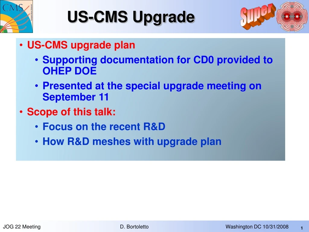
US-CMS Upgrade. US-CMS upgrade plan Supporting documentation for CD0 provided to OHEP DOE Presented at the special upgrade meeting on September 11 Scope of this talk: Focus on the recent R&D How R&D meshes with upgrade plan. Luminosity Upgrade: Issues for CMS.

E N D
US-CMS Upgrade • US-CMS upgrade plan • Supporting documentation for CD0 provided to OHEP DOE • Presented at the special upgrade meeting on September 11 • Scope of this talk: • Focus on the recent R&D • How R&D meshes with upgrade plan JOG 22 Meeting D. Bortoletto Washington DC 10/31/2008
Luminosity Upgrade: Issues for CMS Maybe out of date because of LHC incident • PHASE 1 to start in 2013 with L= 2-4 × 1034 cm-2 s-1 • PHASE 2 to be decided in 2011 with L=8-10× 1034 cm-2 s-1 • US-CMS upgrade plan based on the detector needs to run for sustained periods at luminosities well above 1034cm-2s-1 • Issues that must be addressed • Radiation damage • High occupancy affecting reconstruction or triggering • High occupancy that leads to overflows buffers and to problems with link bandwith • Pileup creating deadtime or affecting trigger • Sensitivity to very rare events • “fakes” via accidentals often involving cosmic rays • CMS is accessible, has been designed to be opened, and therefore “easy” to upgrade JOG 22 Meeting D. Bortoletto Washington DC 10/31/2008
Reduced performance CMS Upgrade Plan Severe degradation Most detectors work even at 3x 1034. Reduced performance Severe degradation JOG 22 Meeting D. Bortoletto Washington DC 10/31/2008
CMS upgrade organization • US CMS has been supporting upgrade R&D and has strong leadership in the CMS upgrade management JOG 22 Meeting D. Bortoletto Washington DC 10/31/2008
US R&D proposal submitted to CMS • Research and Development for CMS tracker in SLHC era Lenny Spiegel (Fermilab), Regina Demina, Yuri Gotra, Sergey Korjenevski (University of Rochester) + others Euoropean groupsSeptember 2006 Approved 06.01 • SLHC Calorimeter Trigger R&D Program University of Wisconsin October 2007 Approved 07.04 • CSC Level-1 Track-Finder Trigger upgrade Florida, Rice, UCLA October 2007 Approved 07.05 • Study of suitability of magnetic Czochralski silicon for the SLHC CMS strip tracker Panja Luukka, Jaakko Härkönen, Regina Demina, Leonard Spiegel October 2007 Approved 07.06 • R&D for Possible Replacement of Inner Pixel Layers With Aims for an SLHC Upgrade Alice Bean , Timothy Bolton, Aaron Dominguez, Wolfram Erdmann, Cecilia Gerber, Roland Horisberger, Angel L´opez October 2007 Approved 07.07 • CSC Endcap Muon Upgrades Contact Person: Jay Hauser October 2007 Approved 07.10 • Reference Link Project For High Speed Optical Data Link R&Ds SMU, Minnesota and OSU October 2007 ApprovalPending 07.11 • The Versatile Link Common Project Francois Vasey and Jan Troska, Physics Department, CERN, Geneva, Switzerland Christian Olivetto and Jean-Marie Brom, Institut Pluridisciplinaire Hubert Curien, Strasbourg, FranceCigdem Issever, Todd Huffman and Tony Weidberg, Department of Physics, Oxford University, United KingdomJingbo Ye, Department of Physics, southern Methodist University, Dallas TX, USA November 2007 Approved 07.12 • 3D detectors for inner pixel layers Daniela Bortoletto/Simon Kwan December 2007 Approved 07.13 • CMS HCAL Calorimeter Electronics Upgrade Drew Baden, University of Maryland December 2007 Approved • Proposal for US CMS Pixel Mechanics R&D at Purdue and Fermilab in FY08 Daniela Bortoletto, Simon Kwan, Petra Merkel, Ian Shipsey, J.C. Yun December 2007 Approved 07.15 • R&D for Thin Single-Sided Sensors with HPK Contact Person: Marcello Mannelli January 2008 Approval Pending 08.01 • Power Distribution System Studies for the CMS Tracker Fermilab, Iowa, Mississippi (Contact Person: Simon Kwan) June 2008 Approved 08.04 • US CMS detector upgrades for PHASE 1 of the LHC luminosity upgrade US CMS (Contact Persons: Daniela Bortoletto, Joel Butler) July 2008 Approved 08.05 OUT of the 22 R&D proposals submitted to CMS JOG 22 Meeting D. Bortoletto Washington DC 10/31/2008
Pixel Upgrade Plans • Baseline: 3 layers (4 layer option) 3 disks in each endcap • Detector technology • Single sided n-on-p sensors (cheaper, more rad-hard?) / n-on-n (fallback) • Evaluating 3D sensors industrialization for innermost layer at 4 cm. • Readout Chip • Double buffer size (in 250 nm CMOS extra 0.8 mm needed for periphery) • Minimal R&D. Design, verification, testing at high beam rates 8-10 months • Mechanical changes • Further gains possible with 130 nm CMOS but R&D needed • Layout, mechanical assembly, and cooling (aim at material reduction of about a factor of 3 in barrel and 2 in forward) • C02 cooling (as in VELO for LHCb) • Low mass module construction and simplified thermal interfaces • Further material reduction can be acheived with on module digitization: • R&D needed: It requires new ADC and Token Bit Manager changes JOG 22 Meeting D. Bortoletto Washington DC 10/31/2008
Development of a replacement plan • Development of layout is allowing to proceed to : • Conceptual design • Small prototyping • Full scale prototyping JOG 22 Meeting D. Bortoletto Washington DC 10/31/2008
Layout under discussion • Developing barrel and disks conceptual design • Fewer module types • CO2 cooling • Barrel: • Only one type (2x8) of modules (2 now) • Two identical half shells • Layer 1 closer to beam-pipe (44mm → 39mm) Kirk Arndt, Purdue • Endcap Disk • Two types (2x8 and 2x4) of modules (5 now) • Possibility of having a removable inner section Modules tilted 20° on both sides of inner(2 x4) and outer (2X8) radius (actively cooled) bulkheads JOG 22 Meeting D. Bortoletto Washington DC 10/31/2008
Forward Pixel Mechanical R&D • Panel Conceptual design • Two substrates with cooling tubes in between. • Material selected for substrate • Low mass TPG laminated with carbon-fiber facing • High thermal conductivity ~ 1600 W/mK, X0 = 18.9 cm • High pressure CO2 cooling/small tubes • The cooling channels will be imbedded in pocofoam • Finite Element Analysis with 200 % heat load shows acceptable performance • Integrated modules to reduce material: Flip chip modules mounted on high heat transfer/stiff material. ∆T = 3.8 C across substrate Purdue -19.4 C FNAL FNAL, CERN, Aachen, Lyon JOG 22 Meeting D. Bortoletto Washington DC 10/31/2008
Pixel Sensor R&D • n-on-p Submission with HPK: • Test different substrates • Different thickness • n-on-p versus n-on-n • Pixel isolation (p-spray and p-stop) • Order should be submitted this month • Turn around time 6 month n-on-p Rad hard up to 3×1015 cm-2 PIRE students • 3D - Submission with Sintef BOLLA, PURDUE 3D Rad hard up to 1016 cm-2 • Shared with ATLAS and MEDIPIX • Implemented 2 variation • 2 columns pixel • 4 columns pixel • Order out • Turnaround time ~ 6 months • Test beam available (FNAL/ROCHESTER/BROWN) et al. • T. Mäenpää, et al. Nucl. Instr. and Meth. A 593 (2008) 523-529. JOG 22 Meeting D. Bortoletto Washington DC 10/31/2008
HCAL Proposal • Replace HB/HE/HF Front End for phase 1 • Change from Hybrid Photo Diode to SiPM • Add longitudinal (HB/HE) and lateral (HF) segmentation • Add shaping (HB/HE) and timing (all) • Keep current fiber plant and front-end services • Big cost and schedule savings but with technical challenges • Replace Trigger/Receiver (VME electronics) for phase 1 • Needed to accommodate HB/HE/HF front-end changes at Phase 1 • Allows for a more powerful system at L1 trigger level • Synergistic with evolution of other CMS subsystems (RCT/Wisc, GCT/IC, ECAL) • Minimal cost • Use same processing board as currently being developed by RCT/GCT • Leverage telecommunications technology • Much less R&D compared to current VME-based TR system • Changes will make a more powerful and robust HCAL • And decrease exposure to the unknown JOG 22 Meeting D. Bortoletto Washington DC 10/31/2008
SiPM R&D • Conceptual Design to connect SiPM to Megatiles • SiPMs (1mm2) are wire bonded to gold pads on glass-fiber substrate • Metal pins locate the cables • Precision molded plastic barrel provides light tightness and proper spacing of fibers above the SiPMs • Array of avalanche photo diodes (“digital” photon detection) • Array 0.5x0.5 up to 5.0x5.0 mm2 • Pixel size can be 10 up to 100m • Are almost “off the shelf” parts • Advantages over HPDs: • 28% QE (x2 higher) and 106 gain (x500 higher) • More light (40 pe/GeV), less photostatistics broadening • Very high gain can be used for timing shaping/filtering • Investigating SiPMs for HO Megatile connector SIPM Princeton JOG 22 Meeting D. Bortoletto Washington DC 10/31/2008
SiPM R&D • Excellent performance in B-field • Good results in initial radiation hardness studies SiPM MAPDs (40 and 15K/mm2) can survive worst case SLHC dose with 2X gain loss. LED Pedestal Pedestal HPD Ion feedback Radiation Dose (SLHC lifetime, 3X safety factor) HB / HE 1013 neutrons, E > 100 keV HO 1011 Discharges JOG 22 Meeting D. Bortoletto Washington DC 10/31/2008
7.5” EMU upgrade • Build ME4/2 chambers (72) • for high-luminosity triggering over h range of 1.1-1.8 • improve m reconstruction • 2) Replace ME1/1 cathode cards with Flash ADC version • restores trigger to h 2.1-2.4 • handles highest rates • 3) Update off-chamber electronics for ME1/1 • accomodate new cathode cards • improve trigger and data handling JOG 22 Meeting D. Bortoletto Washington DC 10/31/2008
EMU R&D: ME4/2 prototype • Uses same technology as other US-built chambers • Technical risks . Costs & schedule well known • The special automated machines are still available • New materials: procured, new panels made and milled • Assembly schedule: • gluing, winding, soldering • Fermilab, Nov-Dec • Prokofiev coordinates (Lanaro visits Fermilab) • tension tests, sealing; FAST site tests • CERN, Mar-Apr • Lanaro and Prokofiev coordinate; plan to be set by mid-October • Make a full production plan updated for prototype experience • Does LHC schedule now allow for deployment of ME4/2 prototype chamber in FY09? JOG 22 Meeting D. Bortoletto Washington DC 10/31/2008
Level-1 Trigger R&D • Phase 1 Goals • Use more fine-grained information from calorimeter & forward muon triggers & improved algorithms exploiting this new information • R&D Conceptual Design of new Regional Calorimeter Trigger • Phase 1 upgrade algorithms being developed • Fully FPGA-based (Virtex-5) • Firmware modules being written Wisconsin • MUON trigger &D • Evaluating high speed serial backplane links • Evaluation of latest Virtex FPGAs & their linktechnologies for muon tracking algorithms • Conceptual Design of CSC Track-Finder • Simplified Sector Processor with Pt assignmentmoved to Muon Port Card • Calorimeter trigger R&D • The GCT Matrix card expected in two weeks at CERN where it will be tested. • Minnesota (J. Mans) has designed and produced a uTCA card with optical links. Currently under test . • Wisconsin is producing a uTCA card to interface uTCA systems with the current CMS DAQ. Receives data from uTCA backplane and transmits them to an FRL via an S-LINK64 interface. The card interfaces with the TTC system to receive clock and trigger information. JOG 22 Meeting D. Bortoletto Washington DC 10/31/2008
US CMS upgrade R&D • Upgrade budget is increasing JOG 22 Meeting D. Bortoletto Washington DC 10/31/2008
The FY09 R&D budget • Develop R&D plan from the ground up by requesting proposals • Proposal are evaluated at CMS level • Focus on phase 1 needs and critical phase 2 issues • Breakdown • Phase 1: 83 % • SiPM: 15% • Pixel mechanics/cooling/ power: 30% • Phase 2: 17% Current budget does not allow investment in ASIC R&D for Phase 2 and track trigger JOG 22 Meeting D. Bortoletto Washington DC 10/31/2008
Conclusions • The feasibility of the SLHC physics program requires detector upgrades able to maintain the performances expected at the standard 1034 cm−2 s−1 luminosity. • The detector upgrades will require detector a strong R&D program • Large interest in the US in R&D program • Excellent coordination with CMS • Moving rapidly to conceptual design for Phase 1 upgrade • Phase 1 replacement/upgrades are a stepping stone for the Phase 2 upgrade • Progress on addressing the largest challenges for phase 2: • Simulation of performance • Understand what is required and how to build it, within a budget • Power delivery and distribution (necessary also for phase 1 to deploy 4th pixel layer) • Provision of triggering data • A vigorous R&D activity for the SLHC phase 1 and phase 2 will entail significant progresses in the area of particle detector developments, and therefore will ultimately have impacts on future machines JOG 22 Meeting D. Bortoletto Washington DC 10/31/2008
Upgrade workshop at FNAL Organization: Butler and Nash • Goals: • Working plan for the phase I • Review progress on Phase II upgrades R&D. • Working groups: • Tracker – Bortoletto & Mannelli • ECAL - Busson • HCAL – Baden • Trigger - Foudas • Muons - Hauser JOG 22 Meeting D. Bortoletto Washington DC 10/31/2008
Tracker: Working group organization • CMS Tracker R&D structure • active for 12-18 months Ryd new power group met in May tracker week for first time JOG 22 Meeting D. Bortoletto Washington DC 10/31/2008
Upgrade Simulation Software • Example strawman geometries as starting points for simulation studies Strawman A Strawman B • Highest priority Simulations studies: • Phase 2 studies to see whether a (buildable) trigger doublet would work, how many are needed and what their parameters should be • Studies with an extra 4th barrel pixel layer and extra forward disk for both Phase 1 and Phase 2 LHC upgrade JOG 22 Meeting D. Bortoletto Washington DC 10/31/2008
Pixel Upgrade Schedule Detail • Expect to finish R&D in mid FY10 • Assume Project funding starts FY10 • 3 disks system completion in 2013 JOG 22 Meeting D. Bortoletto Washington DC 10/31/2008
HCAL Upgrade Schedule Very systematic schedule to get ready for FY14…open questions: • Optimal longitudinal segmentation • Whether/how to add timing capability • Minimize ASIC development • Optimize unused fiber bandwidth FY09 FY10 FY11 FY12 FY13 FY14 SiPM evaluation Prototyping Production QC Installation FE simulation/spec Prototyping Production QC Installation TR readout/interfaces Prototyping Production Testing/firmware dev Installation SiPM = Silicon PMT FE = “Front End” TR = “Trigger/Receiver”, aka “back-end” JOG 22 Meeting D. Bortoletto Washington DC 10/31/2008
Schedule • Assume Project funding starts FY10 • A few details: • Parts procurement can start any time (sooner=better) • Parts procurement chamber production • Parallel to electronics R&D production • Start installation mid-FY12 JOG 22 Meeting D. Bortoletto Washington DC 10/31/2008
SLHC Trigger Conclusions • Phase 1 SLHC Calorimeter & Muon Trigger Conceptual Design Studies underway • Existing trigger limitations & strategies to exploit higher luminosity identified • Provide for evolution into use of tracking triggers in phase 2 • Hardware platform identified & under development • First deployment in CMS in 2009 in Global Cal Trig • Provides for a realistic Basis of Estimate and proof of principle • On track for project baseline in early 2010, prototypes tested in 2011, construction in 2012 & installation in 2013. JOG 22 Meeting D. Bortoletto Washington DC 10/31/2008
Phase 2: Low mass rod • A double pixel module consists of 2 pixel sensors mounted back to back on a Carbon fiber center piece • 20 double pixel modules mounted on a Carbon fiber box beam ~1m long • Use high thermal conductivity materials, i.e. unidirectional C-fiber • Try somewhat radical cooling concepts (for low mass) to start • Initial analysis show sensor temperatures are between -9°C and -38°C with LN cold point only at end of rod. • Further studies and trail runs needed: • Design changes (cold fingers) and Add air flow to reduce gradient substantially • (Just now returning to this after a hiatus for work on Tracker services at Pt 5) JOG 22 Meeting D. Bortoletto Washington DC 10/31/2008
Results of 2008 test beam of heavily irradiated MCz sensors S.Czellar, J.Härkönen, M.Kortelainen, T.Lampén, P.Luukka, M.Maksimow, H.Moilanen, T.Mäenpää, E.Tuominen, J.Tuominiemi, E.Tuovinen, H.Viljanen (Helsinki Institute of Physics) S.Bhattacharya, M.Narain (Brown University)L.Spiegel (FNAL) T.Barvich, A.Dierlamm, M.Frey, F.Hartmann, M.Neuland, H.Simonis, P.Steck (Universität Karlsruhe) B.De Callatay, J.Caudron, T.Keutgen, V.Lemaitre, Ot.Militaru, (Université Catholique de Louvain) A.Kaminskiy, D.Bisello (Università di Padova) B.Betchart, R.Demina, Y.Gotra, D.Orbaker, S.Korjenevski (University of Rochester) Preliminary • Test beam setup description • T. Mäenpää, et al. Nucl. Instr. and Meth. A 593 (2008) 523-529. • Update on Summer 07 results • 225 GeVmuon beam • Location: CERN, SPS North Area H2 beamline • MCz sensors irradiated to 1015 n/cm2 • Comparison to FZ sensors • S/N >20 for MCz after 5.8x10¹⁴ n/cm2 • S/N >10 for MCz after 1.1x10¹⁵ n/cm2 • Demonstrated survivability of the MCz modules up to 1.1x10¹⁵ n/cm2 Preliminary JOG 22 Meeting D. Bortoletto Washington DC 10/31/2008
Geant4 Simulation Software • Software highlights: • Program is working in stand alone mode, with geometry and run time parameters specified via plain-text parameter files. • Run-time geometry changes can be specified. Program will perform a data run with each specified value, and the results are compared. Example of a run time geometry change. The support structure depth is changed from 2 mm to 10 mm in increments of 1 mm. Plot shows variance vs. structure depth for 5000 event runs. Example of a double-double superlayer module simulation. R. Rossin / S. Swain / J. Lamb, October 2008
7.5” Task 2) New ME1/1 Cathode Cards • Propose digital card: flash ADCs for every channel • Much better rate capability • Parts cost is now similar • Proposed deployment: • 514 new cards ME1/1, 360 current cards ME4/2 • Handle the highest particle rates • Restore full ME1/1a triggering and readout to h range 2.1-2.4 • (ganging strips 3:1 there now) JOG 22 Meeting D. Bortoletto Washington DC 10/31/2008
DMB TMB Copper connectors Copper connectors Task 3) Updated off-chamber electronics for ME1/1 • Two boards (DMB and TMB), 72 of each required • Optical replaces copper (unreliable at 15m length for ME1/1) • New programmable gate arrays (FPGAs) • Dramatically improve triggering and data handling JOG 22 Meeting D. Bortoletto Washington DC 10/31/2008
20 bits @ 80 MHz =1.6 Gbps FIBERS CERNTransmitter 40 bits @40 MHz HPD Shield Wall QIE QIE QIE QIE QIE QIE Trigger/Receiver (TR) S-Link: 64 bits @ 25 MHz Trigger/Receiver (TR) Trigger Primitives READ-OUT Crate • 1 PC Interface SBS CLK D C C H T R H T R H T R Level 1 TRIGGER Rack CPU • 12 HTRs • 1 Clk board • 2 DCC TTC FRONT-END Readout Box (RBX) On detector analog optical signals from HCAL CCA GOL CCA GOL CCA FE MODULE JOG 22 Meeting D. Bortoletto Washington DC 10/31/2008
TR Replacement • Accommodate new FE system • Longitudinal segmentation means more channels • Retaining current fiber plant has big cost and schedule advantages • More FE data per tower, therefore need to transmit at higher speeds, therefore new receivers • Digital filtering of data in FPGA may be necessary • More advanced trigger schemes to optimize physics at high luminosities • Need for more processing in FPGAs • Take advantage of commercial technologies • Cell phone tower DAQ, fast digital I/O on backplanes, etc • Synergy between new HCAL and CMS ECAL/trigger upgrade efforts • Maryland, Minnesota, Boston U., Wiscsonsin, LANL, Imperial College, Cern JOG 22 Meeting D. Bortoletto Washington DC 10/31/2008
Telecommunications Computer Architecture (TCA) • Largest specification effort ever attempted by the PCI Industrial Computers Manufactures Group • Over 100 companies • Targets next generation of carrier grade telecommunications • Optimized for high speed interconnects, next generation processors, improved reliability and serviceability • Very low risk in going to this standard JOG 22 Meeting D. Bortoletto Washington DC 10/31/2008
CO2 R&D • CO2 properties match silicon detector applications • Low viscosity and low density difference between liquid and vapor is ideal for micro channels (d<2.5mm) • Great saving in material budget liquid (CO2 is ~ 1.03 g/cm3 compared to 1.76 g/cm3 of C6F14) • Small area for heat transfer need to route enough tubes for sufficient thermal contact with pixel modules • Ideal for serial cooling of distributed heat sources • Radiation hard • Optimal operation temperature -40°C to +20°C • “No showstoppers” for existing CMS pipes (aim for maximum of 40 Bar, Pipes rated to 150 Bar) • CO2 cooling excellent candidate for upgrade • We are constructing a CO2 cooling system for lab bench testing Already used by LHCb VELO detector LHCb CO2 cooling tube JOG 22 Meeting D. Bortoletto Washington DC 10/31/2008
Luminosity assumptions Peak Luminosity ( 1034 cm-2 s-1 ) Luminosity (fb-1) • Expected peak (left) and integrated luminosity (right). The normal (blue, presented by Garoby at LHCC), optimistic(red), and pessimistic(green) scenarios have been determined by varying the effective running time between 5M and 7.5 M second/year. We assume a shutdown in 2017 before the phase 2 upgrade, based on recent discussions with LHCC (could be 3 months earlier) LHC Phase 1 LHC 800 fb-1 Phase 1 R. Garoby LHCC July 1 2008 300 fb-1 JOG 22 Meeting D. Bortoletto Washington DC 10/31/2008
US CMS Phase 1 Upgrade Matches US expertise
SIPM Dynamic Range 10 mm square (10K pixels/mm2) plenty for dynamic range for HCAL. But other considerations like finite recovery time eased by having more pixels. Exploring 15K and 40K per mm2