Download
1 / 10
100 likes | 236 Views
DS4T5 – Beam forming at the patch level. Primary objectives: Compare the cost effectiveness of analogue and digital solutions for wide-band beam forming; Digital Beam-former solutions: Evaluate the cost-effectiveness of different DSP solutions; Demonstrate a single-board, beam-forming setup;

E N D
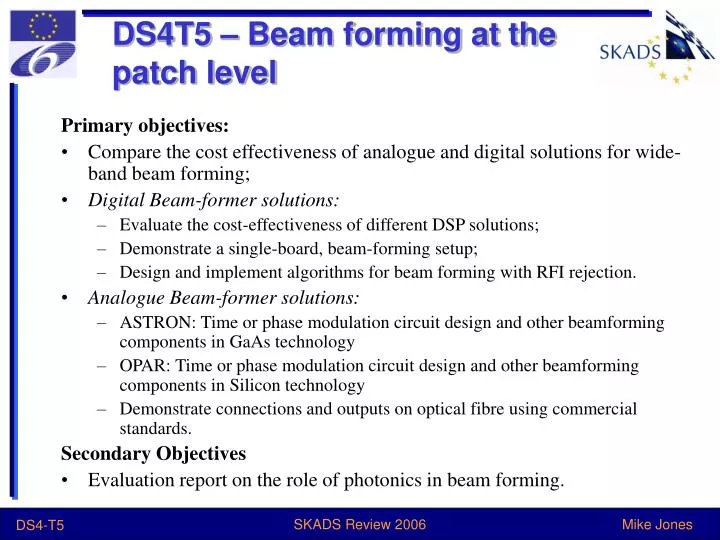
DS4T5 – Beam forming at the patch level Primary objectives: • Compare the cost effectiveness of analogue and digital solutions for wide-band beam forming; • Digital Beam-former solutions: • Evaluate the cost-effectiveness of different DSP solutions; • Demonstrate a single-board, beam-forming setup; • Design and implement algorithms for beam forming with RFI rejection. • Analogue Beam-former solutions: • ASTRON: Time or phase modulation circuit design and other beamforming components in GaAs technology • OPAR: Time or phase modulation circuit design and other beamforming components in Silicon technology • Demonstrate connections and outputs on optical fibre using commercial standards. Secondary Objectives • Evaluation report on the role of photonics in beam forming. SKADS Review 2006
Analogue Beam Forming OPAR: low cost analogue beamformer in Silicon.(J Pezzani) • 0.25 µm SiGe technology from Philips Semiconductors • good trade-off between price and performance • 3 bits phase shifters - 360° phase variation with 45° step • gain changed with 0.6 dB step on a 3 dB range with a 3 bits control • A full digital serial interface is built on the chip • Manufacturing of the chip and measurements will be made in the next months. • Results from these measurements will be used for a second iteration Layout of 4 channel – 2 beams first prototype beamformer chip SKADS Review 2006
Analogue Beam Forming Analogue Beam Former in GaAs (ASTRON) • Beam forming design for EMBRACE • See DS5 report (Parbhu Patel/Dion Kant) SKADS Review 2006
Photonic Beamforming Photonic integrated circuit (PIC) beamformer(ASTRON) (P Maat) • Broadband, ns range, true time delay - (integrated) optical ring resonators • Continuously tunable effective delay controlled by tuning coupling coefficients between the waveguide and the ring resonator, and the round-trip phase shifts of the ring resonator. • First goal: develop and study a tile beamformer system using PIC beamformer component. • Next, the photonic beamfomer will be applied in a tile demonstrator (EMBRACE). • Work so far: • specification of the requirements for the photonic beamformer. • development of a low cost, high performance optical analogue link • First photonic beamformer chip samples will become available in the autumn of 2006. SKADS Review 2006
Digital Beam Forming Digital beam forming also part of EMBRACE (DS5) (+LOFAR…) • Beam forming for All-Digital Aperture Array (M Jones Oxford, A Faulkner Manchester, P Alexander Cambridge) • 2-PAD demonstrator • Can we build a practical (affordable!) all-digital system? • Try to design architecture for flexible beam forming system – Moore’s law will catch up • Use digital system to ‘correct’ analogue errors: may be essential for dynamic range spec (eg polzn purity) • Multiple fields of view, up to all sky: may be essential for dynamic range spec (bright sources) SKADS Review 2006
Tile Processor 4-bit, 1.2GS/s, Element Data Horiz. Polarisation Vert. Polarisation Freq. Split. n Chips 210 Polyphase filter 210 8-bit Preset coefficients 210 Polyphase filter 210 8-bit Preset coefficients X X 1 pair of 256 elements … … 210 spectral channels 0 4-bit 1.2MS/s 1023 0 1023 Linear Matrix Mult. to ‘correct’ Element polarisation at specific freq. (1 of 210) ….. ….. 4-bit data 255 255 ~1.2MS/s 0 0 Inter-element scaling (matrix mults) Inter-element scaling (matrix mults) ….. ….. 255 255 ~1.2MS/s 0 0 16 x 16 element, 2-D FFT (1 of 210) Horiz. pol 16 x 16 element, 2-D FFT (1 of 210) Vert. pol ….. ….. FOVs 255 ~1.2MS/s 8-bit data: 0 256 8 FOV selector (1 of 210) 256 8 FOV selector (1 of 210) 7 0 7 8-bit data: 0 Linear Matrix Mult. to ‘correct’ Field-of-View polarisation at specific freq. (1 of 8) ….. ….. 255 ~1.2MS/s 210/m 1 Data multiplexer (1 of 8) 210/m 1 Data multiplexer (1 of 8) 2-D FFT, mChips Field of View 1 of 8 Dual Polarisation, 8 bit 1.2/m GS/s SKADS Review 2006
Tile Processor 4-bit, 1.2GS/s, Element Data Horiz. Polarisation Vert. Polarisation Freq. Split. n Chips 210 Polyphase filter 210 8-bit Preset coefficients 210 Polyphase filter 210 8-bit Preset coefficients X X 1 pair of 256 elements Multiplexed data from elements brought onto frequency splitter chips – both polarisations from an element always on the same Freq. Splitter chip. … … 210 spectral channels 0 4-bit 1.2MS/s 1023 0 1023 Each polarisation for each element is split into 1024 spectral bands, corrected for amplitude and phase if necessary. Total 256 pairs of polyphase filters Linear Matrix Mult. to ‘correct’ Element polarisation at specific freq. (1 of 210) Each element at each spectral channel has its polarisation purity optimised at ONE selected scan angle. ….. ….. 4-bit data 255 255 ~1.2MS/s 0 0 Inter-element scaling (matrix mults) Inter-element scaling (matrix mults) ….. ….. 255 255 ~1.2MS/s 0 0 The corrected polarisation data as spectral channels are multiplexed as 256/nfor each link to the 2-D FFT chips. 16 x 16 element, 2-D FFT (1 of 210) Horiz. pol 16 x 16 element, 2-D FFT (1 of 210) Vert. pol ….. ….. FOVs 255 ~1.2MS/s 8-bit data: 0 256 8 FOV selector (1 of 210) 256 8 FOV selector (1 of 210) 7 0 7 8-bit data: 0 Linear Matrix Mult. to ‘correct’ Field-of-View polarisation at specific freq. (1 of 8) ….. ….. 255 ~1.2MS/s 210/m 1 Data multiplexer (1 of 8) 210/m 1 Data multiplexer (1 of 8) 2-D FFT, mChips Field of View 1 of 8 Dual Polarisation, 8 bit 1.2/m GS/s SKADS Review 2006
Tile Processor 4-bit, 1.2GS/s, Element Data Data from ALL 256 elements over a chosen frequency range is brought onto one 2-D FFT chip Horiz. Polarisation Vert. Polarisation Freq. Split. n Chips 210 Polyphase filter 210 8-bit Preset coefficients 210 Polyphase filter 210 8-bit Preset coefficients X X 1 pair of 256 elements … … 210 spectral channels 0 4-bit 1.2MS/s 1023 0 1023 Opportunity to correct any Tile level variations and mutual coupling between elements at each frequency Linear Matrix Mult. to ‘correct’ Element polarisation at specific freq. (1 of 210) Form ALL 256 FOVs (beams) over each spectral channel ….. ….. 4-bit data 255 255 ~1.2MS/s 0 0 Inter-element scaling (matrix mults) Inter-element scaling (matrix mults) Select 8 FOVs from possible 256. This is done with each spectral channel ….. ….. 255 255 ~1.2MS/s 0 0 Further refining polarisation purity for the selected FOVs. This can be done specifically for all 8 FOVs at each spectral channel 16 x 16 element, 2-D FFT (1 of 210) Horiz. pol 16 x 16 element, 2-D FFT (1 of 210) Vert. pol ….. ….. FOVs 255 ~1.2MS/s 8-bit data: 0 256 8 FOV selector (1 of 210) 256 8 FOV selector (1 of 210) Multiplex all the spectral channels processed on the 2-D FFT chip for transmission to FOV processor 7 0 7 8-bit data: 0 Linear Matrix Mult. to ‘correct’ Field-of-View polarisation at specific freq. (1 of 8) ….. ….. 255 ~1.2MS/s 210/m 1 Data multiplexer (1 of 8) 210/m 1 Data multiplexer (1 of 8) 2-D FFT, mChips Field of View 1 of 8 Dual Polarisation, 8 bit 1.2/m GS/s SKADS Review 2006
Key points • Initial frequency split → channel bandwidth low → get many elements on one processing chip • FFT beamforming gives you the whole sky (put eg many beams on bright sources for calibration) • Trade beam area/bandwidth at constant total data rate • Need serious processing chip • Chip developers say processing is OK on SKA timescale • Problem is I/O! - on chip scale as well as station-correlator SKADS Review 2006
Future • Rest of 2006: • Continue paper designs/blue sky thinking • Recruit hardware and algorithm development team • 2007 • Prototype key hardware elements • Algorithm development • 2008 • Q1: 2-PAD final design • Build 2-PAD beam forming • 2009 • Results and reports SKADS Review 2006