Download
1 / 16
160 likes | 297 Views
LM monitor and background test JUNE 13 2006 -- Lu Jun-guang. 1. introduction 2. goal of luminosity monitor 3. Structure of BESII Luminosity detector 4. Calculation of the luminosity 5. MC of luminosity detector

E N D
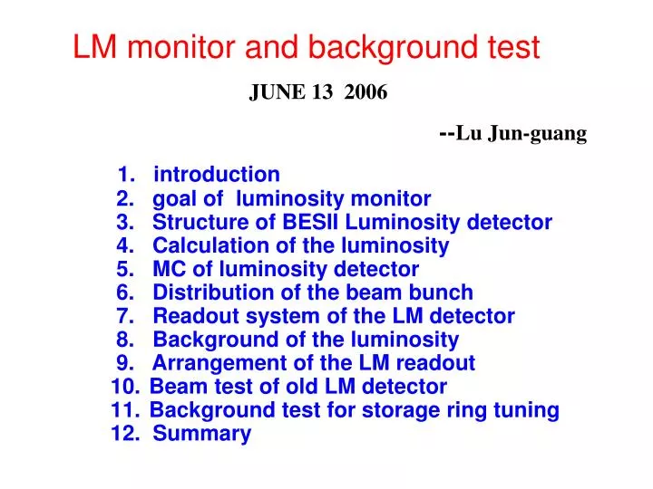
LM monitor and background testJUNE 13 2006 --Lu Jun-guang 1. introduction 2. goal of luminosity monitor 3. Structure of BESII Luminosity detector 4. Calculation of the luminosity 5. MC of luminosity detector 6. Distribution of the beam bunch 7. Readout system of the LM detector 8. Background of the luminosity 9. Arrangement of the LM readout • Beam test of old LM detector • Background test for storage ring tuning 12. Summary
introduction • CPM of BEPCII 2006/9—07/1: single beam (e-) running. Setup a group scintillator detector for test background in the IP region. 07/02---07/06:BEPCII storage ring tuning and colliding. # Setup BESII luminosity detector and Zero degree fast Cherenkov Luminosity monitor work in the online data. # setup a group scintillator detector for test background in the position region of inner MDC. 07/07--: After BESIII move in colliding region # Endcap crystal calorimeter provide luminosity data for BESIII and BEPCII, work in the online data. # Zero degree fast Cherenkov Luminosity monitor provide luminosity data for BEPCII.
Luminosity monitor (for BEPCII) • The major goal of the LM is to measure the colliding luminosity of BEPCII storage ring L=Nx1030 ~1032 cm-2s-1, precision: <15% • setup the BESII LM to based on detection of Bhabha ( e+e- e+e-)scattering at small angle, the counter rate of Bhabha events with a time constant of 10s, report it to operators fast enough that it could be used in tuning procedures. • With two luminosity system: 1. BESII luminosity detector + VME by IHEP 2. Zero degree fast Cherenkov luminosity detector by USTC to based on the detection of e+e- e+e-
Structure ofBESII luminosity detector (CALTECH,U.S.A.) P-position: (86,0,1130)
Structure ofBESIIluminosity detector PMT: 1” fine mesh PMTP,C counter: Scintillator:SCSN-81 (th:8mm) from BicronS counter: Tungsten (3.5mm) & scintillator (4mm) sandwich total thickness 12X0 (12 layers) In a aluminum box S Readout : with WLS fiber(2mm) embed in thegroves of scintillator
Calculation of the luminosity Luminosity of the storage ring: C=3.11×1036 , f —frequency of collding(s-1), Bhabha ( e+e- e+e-)scattering at small angle Relation of the Bhabha rate with luminosity
MC of luminosity detector MC: BESIII-Genbes Position: X=70,Y=0, z=400mm, S cut: E = 1.55GeV, (0.7<E>2.3 GeV) P,C cut: dE/dX =1.6 MeV, (>200KeV) B: = 640/E2 (nb) ( P counter ) R: ~ 5 (L=2X1031 cm-2 s-1 )
Distribution of the beam bunch T0 question: 1, the beam cycle signal (802ns/one) come from BEPC,it delay to much for LM 2, pickup signal, it need to discriminate and cut multi-pulse.
Readout system of the luminosity detector VME-TDC V775N-16channel: measuring region: <1.2s; precision: 300ps; 32 multievent buffer
Background of the Luminosity • Normal colliding: T1,3 or 2,4 =0 ns; Ti = Nx8ns • Background (A,B and D): T1,3 or 2,4=02.5 ns; Ti = Nx8-2.5ns • Background C: T1,3 or 2,4 =0 ns; Ti = Nx8ns • Demand timing resolution: t 500ps to identify a Ti ~2.5ns
Arrangement of the luminosityreadout • Online LM data : Bhabha events: Background events : (P1·S1) ·(C3·S3) (P1·S1) ·(C2·S2) (P2·S2) ·(C4·S4) (P1·S1) ·(C4·S4) (P3·S3) ·(C1·S1) (P2·S2) ·(C1·S1) (P4·S4) ·(C2·S2) (P4·S4) ·(C3·S3) N = Normal events - background events • Li = Ci X Ri / b ∫Lidt/4 one LM data for 10s Ci correct factor by offline analyses • Offline : 1. timing cut and Eth cut to data analyses 2. other correct factor of dead time, MC and survey error 3. set Ci correct factor into next online LM data
Beam test of old LM detector QADC distributions of Pi and Ci counter for 1 GeV e- beam energy Pi Ci
Beam test of old LM detector QADC distributions of Si counter for 1 GeV e- beam energy: E/E ≤ 22 % Timing resolution: Tpc=600 ps t=400ps (for P and C)
Background test for storage ring tuning • Setup a group scintillator detector at the inner MDC part • Setup a group PIN silicon radiation monitor (by QHU) • Measurement beam background rate on tuning and colliding • Provided a judgment to insure the MDC inner wires be no breakdown when BESIII move into colliding region .
Summary • We will rebuild BESII LM detector provide online luminosity data to based on Bhabha evevst at small angle for the storage ring colliding tuning. • Arrangement of the luminosity system, use VME-TDC module get detector time data to identify the normal events and background on the multi-bunch colliding of BEPCII • Beam test results forBESII LM detector shown the energy resolution and the timing resolution are passable to use to the goal • We will setup scint-detector and radiation monitor to measure beam background on the storage ring tuning and colliding,provided a judgment to insure the MDC inner wires be no breakdown when BESIII move into colliding region .