Download
1 / 8
80 likes | 167 Views
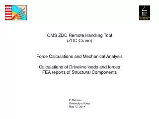
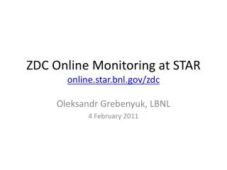
ZDC Remote Handling System. March 10, 2011 Project Status and Forward Planning Technical Implementation Group Meeting Paul Debbins University of Iowa. Model Crane Installed on (-) TAN. Crane in Standby condition, parking position when not in use.

E N D
ZDC Remote Handling System March 10, 2011 Project Status and Forward Planning Technical Implementation Group Meeting Paul Debbins University of Iowa
Model Crane Installed on (-) TAN Crane in Standby condition, parking position when not in use Crane installation and testing underground at Pt5 - Provided a method to validate all geometric considerations - Provided practice in assembly and handling of system underground * Generate a sequence of assembly/operation steps with associated times and positions for CERN Transport and RadioProtection groups.
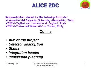
Position shown is past full movement Payload Crane in stages of operational movement, with Attached representative payload
Hard Clearances R(-) Min. Payload - TAN (transport side) Min. Actuator – TAN (QRL side) L(+) Vertical to ceiling services No collisons to hard artifacts of Tunnel and TAN. Measured clearances in excellent agreement with Virtual Models – confidence in the manual survey and its translation in to CAD L(+) side vertical clearance was most critical. Model validates several cm available space to expand vertical clearances in system – esp. min vertical space to BRAN Actuator spindle protection tube clearance to tunnel wall services – plenty, incl. anti-runout device extra length of tube. No collision with QRL platform.
Soft Clearances Rotary Jack input drive coupling axle 1 Interference with rotary jack interconnect input drive axle. Discussed with E. Bravin. Simple to move gas hose. No interference of crane with cable trays on either side. ZDC cabling is to be re-done, to use single multi-contact connectors for all signals, HV, and Laser. This substantially reduces the time spent (un)cabling during operations (ALARA). Eliminates the good probability of mis-cabling, and reroutes the cables into clean pathways clear of crane and human movements in the area.
BRAN Vert. Clearance Vertical clearance to BRAN: crane carrier beam Fully raised, 625mm clearance, 615mm vertical Carrier travel to lowest pos + 10mm clearance Above beam => “0” clearance to BRAN survey ball Model testing allows to provide for 20mm additional Clearance. Crane Design modified to provide Additional BRAN overhead clearance. Survey balls are removable and also provide Useful fixation points for attachment to crane for BRAN lifting. Discussed this option with E. Bravin BRAN survey points BRAN group must provide engineering to design and implement a fixture attaching the BRAN to the crane for BRAN removal. This is NOT a Univ. of Iowa responsibility. BRAN mounting in slot is also in need of remedy – BRANS are placed in different locations in the slot. 1 BRAN is keyed into Locating holes in TAN, the other is ‘free – floating’. Both units need to be keyed at consistent locations, with proper clearances To adjacent elements (ZDC) when mounted in TAN
Crane Production Readiness Crane Model Testing - - - > Allows final commitment to geometry With increased Vertical Clearances Final Geometry allows exact commitment To actuator specifications - Actuator specs sent to supplier to generate a current order then Referred to KU and ordered. ~ 1 week Some Structure Design modifications – DONE Modified designs sent to welding fabricators for Comments/mods to suit their best practices - DONE Crane model ported to Simulation / Analysis environment To allow Force determination and FEA analysis of complete model 50% complete Order Steel Structure Fabrication ~ 2 Weeks Generate Mechanical Study of Safety
Additional preparation for testing Sarcophagus Design - DONE - Need to send to KU for production - 1 Sarco needed for testing “BARS” payload (S.Steelabosrber) - Design DONE - Send to A.L Perrot for referral to CERN shops for fabrication Sarco Payload Above Ground Testing of System - Begin July 2011 Platform • Construction of Testing Platform • Where? Pt5? Pawel, CMS TC • How ? Design concepts exist • Need to discuss and refine Crane